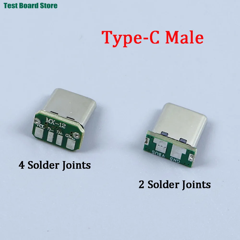
USB-C Male Vertical Patch Board Connector
Official Store Deal
Expert Analysis Overview
Precision USB-C Integration for Custom Electronics
The USB-C Male Vertical Patch Board Connector is a specialized component designed for direct integration into custom printed circuit board (PCB) applications. This connector is not a finished cable or adapter; it is a raw, board-mountable male USB-C plug. Its primary function is to provide a robust and standardized USB-C interface for DIY electronics projects, device repair, or bespoke hardware development where space and direct board connection are paramount.
Connector Variants and Electrical Integrity
The product offers two distinct variants: a 4-solder joint and a 2-solder joint configuration. The 4-solder joint variant, as depicted in the technical drawings, typically includes connections for VBUS (power), D+ (data), D
Unlike generic USB-C connectors that might offer a full 16-pin or 24-pin array for advanced USB 3.1/3.2 features, these simplified versions prioritize ease of integration for specific, less demanding applications. The reduced pin count simplifies the soldering process, making it more accessible for hobbyists and small-scale manufacturers. This design choice inherently limits the connector to USB 2.0 speeds and basic power delivery, which is a deliberate trade-off for its compact form factor and simplified integration.
Mechanical Durability and Mounting Considerations
Each connector features a metal housing that encases the internal contacts, providing structural rigidity and shielding against electromagnetic interference. The vertical patch board design means the connector stands upright from the PCB, which can be advantageous in designs where horizontal space is limited. The solder joints themselves are the primary mechanical anchor points to the PCB. A secure solder joint ensures both electrical continuity and physical stability, preventing accidental dislodgement during use.
Compared to through-hole components that offer greater mechanical strength due to pins passing through the board, these surface-mount style connectors rely heavily on the quality of the solder joint. For applications involving frequent plugging and unplugging, additional mechanical support, such as epoxy potting or a custom enclosure, may be necessary to prevent stress on the solder pads. The compact footprint minimizes the required board space, a significant benefit for miniaturized devices.
Application Scenarios and Electrical Safety
These connectors are ideal for creating custom charging modules, data logging devices, or small embedded systems that require a USB-C interface for power input or basic data communication. The simplified pinout of the 2-solder joint variant is particularly suited for power-only applications, where only VBUS and GND connections are needed. This reduces complexity and potential points of failure for dedicated charging ports.
When integrating these components, adherence to proper electrical safety standards is paramount. Overcurrent protection, correct voltage regulation, and robust grounding practices must be implemented on the host PCB. Unlike pre-assembled cables with integrated safety features, these raw connectors place the responsibility for circuit protection squarely on the designer. The visible solder pads are small, demanding precise soldering techniques to avoid bridging connections or creating cold joints, which can lead to intermittent operation or, worse, short circuits.
Value Proposition for Custom Builds
The availability of these connectors in various pack sizes (1, 5, or 10 pieces) offers flexibility for both prototyping and small-batch production. The cost-effectiveness of these individual components allows developers to integrate modern USB-C connectivity without the expense of custom-fabricated boards or more complex connector solutions. This enables rapid iteration and testing of designs, accelerating development cycles for new electronic products.
Unlike proprietary charging ports or older micro-USB connectors, the adoption of USB-C ensures broad compatibility with contemporary power adapters and data cables. This future-proofs custom devices to some extent, aligning them with current industry standards. The ability to source these components individually empowers engineers and hobbyists to repair existing devices with damaged USB-C ports, extending the lifespan of valuable electronics.
The Importance of Proper Soldering Technique
For any electrical component, the quality of the solder joint directly impacts performance and longevity. These small USB-C connectors require a fine-tipped soldering iron and steady hands. Insufficient heat can lead to a 'cold joint,' characterized by a dull, grainy appearance, which results in poor electrical conductivity and mechanical weakness. Conversely, excessive heat can damage the connector's internal plastics or lift the PCB pads, rendering the component unusable. A proper solder joint will appear shiny and smooth, forming a concave fillet between the pin and the pad.
Consider the thermal mass of the connector's metal housing. This housing can act as a heat sink, requiring slightly more heat or a longer dwell time to achieve a good joint on the ground connections. However, care must be taken to avoid overheating the data pins, which are more delicate. The small pitch of the pins necessitates careful alignment and flux application to prevent solder bridges, especially on the 4-pin variant where pins are closer together. A magnifying glass or microscope is highly recommended for inspection.
Ensuring Long-Term Reliability
Reliability in custom electronics hinges on every component, and the USB-C connector is a frequent point of interaction. The choice between the 2-solder and 4-solder joint variants should be driven by the specific functional requirements of the end device. For simple power input, the 2-pin version minimizes complexity and potential failure points. For basic data transfer, the 4-pin variant provides the necessary D+/D
When designing the PCB layout, ensure adequate clearance around the connector to facilitate easy soldering and prevent accidental short circuits. The vertical orientation means the connector's height must be factored into the overall enclosure design. Proper strain relief for any connected cable is also critical to prevent mechanical stress from being transferred directly to the solder joints, which is a common cause of failure in frequently used ports. This attention to detail in both electrical and mechanical design ensures the longevity and safe operation of the final product.
Imagine the satisfaction of completing a custom electronic project, knowing that its power and data interface is built with precision and reliability. These USB-C connectors provide the foundational capability for such endeavors, allowing for seamless integration into your next innovative device, ensuring stable power delivery and dependable data transfer for years of consistent operation.