USB 3.1 Type C Female Panel Mount Connector with Screw Fixing
Official Store Deal
Expert Analysis Overview
Precision Integration: USB 3.1 Type C Panel Mount Connectors
USB 3.1 Type C Female Panel Mount Connectors are essential interface components designed for integrating modern, reversible power and basic data connectivity into custom electronic enclosures and DIY projects. These units provide a robust and stable connection point, critical for applications where reliability and physical security are paramount. The design prioritizes mechanical stability over the full spectrum of USB 3.1 capabilities, focusing on secure installation.
Engineering for Enduring Connectivity
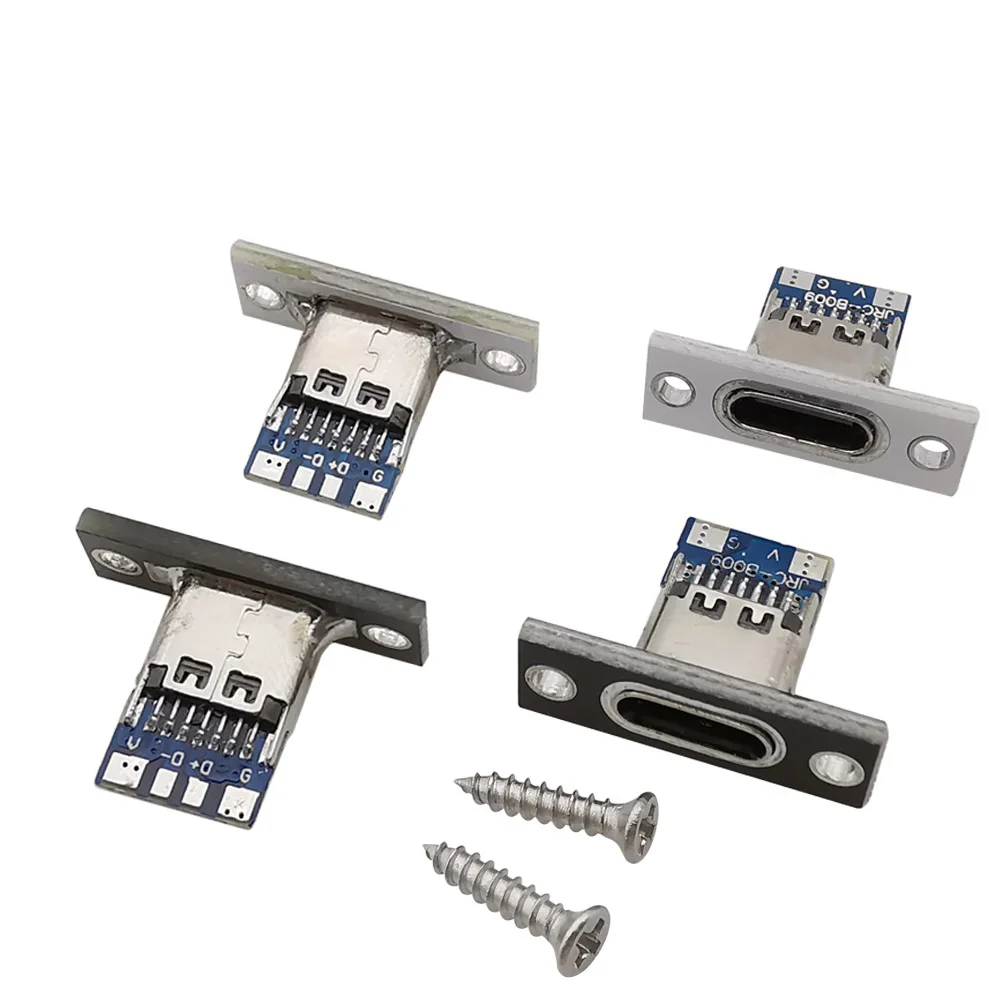
The primary visual characteristic of these connectors is the integrated screw fixing plate. This metal plate, available in both silver and black finishes, provides a substantial anchor point. It is a critical design element. This robust mounting mechanism directly addresses the common issue of unsecured or flimsy USB ports in custom builds. Unlike connectors that rely solely on PCB solder points for mechanical stability, this design distributes stress across a larger surface area. It prevents port damage from repeated cable insertions and removals. This significantly reduces the risk of internal wiring failures. Mechanical integrity is paramount.
Compared to standard through-hole or surface-mount USB connectors, which can be prone to detachment under strain, these panel-mount units offer superior long-term durability. This ensures a consistent electrical connection over the product's lifespan. The physical security provided by the screw mount mitigates the pain point of accidental disconnections or port damage, a frequent frustration in high-traffic or industrial environments. This is a practical solution.
Connectivity Versatility and Electrical Integrity
These connectors are offered in two primary pin configurations: 2-pin and 4-pin. The 2-pin variant typically provides VBUS (power) and GND (ground), making it ideal for dedicated charging applications. This simplifies power delivery. The 4-pin version expands functionality by adding D+ and D
It is crucial for a certified electrician to understand the implications of these pin counts. While the physical Type C form factor is present, these specific variants do not support the full range of USB 3.1 Gen 2 speeds, video output, or advanced Power Delivery (PD) protocols. These advanced features require additional pins and more complex internal circuitry. For applications demanding only power or basic data, these connectors offer a streamlined and cost-effective solution. They are fit for purpose.
Electrical integrity is paramount. The small printed circuit board (PCB) integrated with the connector facilitates direct soldering of wires. This requires careful attention to solder quality and wire gauge. Using an appropriate wire gauge for the intended current load is essential to prevent overheating and potential fire hazards. Verification of wire gauge accuracy is a non-negotiable step. The visible terminals appear well-defined, suggesting a reliable surface for solder adhesion. Proper soldering ensures low resistance connections. This maintains efficiency.
Material Science and Durability Assessment
The visible materials imply a focus on functional durability. The metal mounting plate provides structural rigidity and heat dissipation. This is a good sign. The PCB itself, while compact, appears to be of standard quality for such components, with clear markings (e.g., "RC-B009" visible on some units) that can assist in identification or troubleshooting. The screws provided are self-tapping Phillips head, indicating ease of installation into various panel materials. These are common fasteners.
From an electrical perspective, the quality of the metal used in the connector housing and the mounting plate is important. While specific material composition is not provided, the visual appearance suggests a robust alloy capable of withstanding typical environmental stresses. The finish, whether silver or black, likely offers some degree of corrosion resistance. This extends operational life. The compact nature of the PCB minimizes potential points of failure, though proper insulation from the mounting plate is critical if the plate is conductive, which is often the case with metal components. Electrical isolation prevents short circuits.
Compared to purely plastic-housed connectors, the metal mounting plate significantly enhances the product's resilience against physical impact and strain. This translates to a longer service life in demanding applications. The overall construction suggests a component designed for integration into systems where reliability cannot be compromised. This is a sound investment.
Installation Precision and Operational Considerations
Integrating these panel-mount connectors requires precise execution. A clean, accurate panel cutout is essential for a flush and secure fit. The caliper measurements shown in the product images (e.g., ~14.30 mm width, ~20.10 mm length) highlight the need for exact dimensions. This ensures proper alignment. The mounting holes must also be drilled accurately to prevent misalignment or stress on the connector. Incorrect drilling can compromise the physical integrity of the installation.
Soldering the power and data lines to the small PCB pads demands a steady hand and appropriate soldering equipment. Cold solder joints or bridging between pads can lead to intermittent connectivity, power loss, or even short circuits. Ensuring proper safety standard compliance during installation is paramount. Always disconnect power before commencing any wiring work. This prevents electric shock. The small size of the pads necessitates fine-tipped soldering irons and good lighting. This improves precision.
In a scenario where these connectors are used in an enclosure, proper cable management is also vital. Securing internal wiring prevents strain on the solder joints and ensures long-term reliability. The robust nature of the panel mount means the weakest link often becomes the internal wiring if not properly managed. This is a common oversight. Careful planning is key.
Application Spectrum and Value Proposition
These USB-C panel mount connectors are ideally suited for a range of applications requiring a fixed, accessible USB-C port. Consider custom power banks, where a secure charging input is necessary. Embedded systems, industrial control panels, or hobbyist projects like custom arcade cabinets or retro gaming consoles can benefit immensely. They offer a clean aesthetic. The value proposition lies in their ability to provide a durable, standardized interface that elevates the professional appearance and functional reliability of any custom build. This enhances user experience.
Unlike generic, unmounted USB ports that can be easily damaged or dislodged, these connectors offer a permanent and robust solution. The initial investment, while slightly higher than a bare PCB connector, is offset by the reduced risk of costly repairs or system failures down the line. This represents a significant return on investment. The inclusion of mounting screws further streamlines the assembly process, saving time and effort for the installer. Efficiency is improved.
Imagine completing a custom electronics project, knowing that every external port is not only functional but also physically secure, capable of withstanding years of regular use. The clean, integrated look of a panel-mounted USB-C port adds a professional touch, reflecting meticulous craftsmanship. This connector ensures your device maintains reliable power and data transfer, free from the common frustrations of loose or damaged connections. Your work will stand the test of time. This is the assurance these components provide, allowing you to focus on the innovation within your projects, confident in the integrity of your external interfaces.