USB 2.0 Type-A Female Right-Angle DIP PCB Connector
Official Store Deal
Expert Analysis Overview
The USB 2.0 Type-A Female Right-Angle DIP PCB Connector is a fundamental electronic component, critically designed for direct integration onto printed circuit boards, serving as a robust interface for USB 2.0 peripherals. This connector is engineered for repair technicians and hobbyists who require a reliable and space-efficient solution for data and power transmission in various electronic devices. Its specific right-angle, Through-Hole Technology (THT) design facilitates secure mechanical attachment and electrical connection, making it an indispensable part for both new designs and equipment refurbishment.
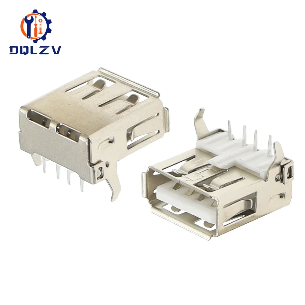
Visible imagery reveals a connector constructed primarily from a metallic outer shell, likely nickel-plated steel or a similar alloy, encasing a white plastic insulator block. This metallic shielding provides essential electromagnetic interference (EMI) protection, crucial for maintaining signal integrity in noisy electrical environments. The robust outer casing also offers significant physical protection against mechanical stress, a common point of failure for frequently used ports.
Such material choices directly impact the connector's longevity and performance in real-world applications. A sturdy metal shell prevents deformation from repeated insertions and removals of USB devices. The internal plastic insulator, typically a high-dielectric polymer, ensures proper isolation between the electrical contacts, preventing short circuits and maintaining the integrity of the data and power lines. This construction choice is standard for reliable connectivity.
Unlike many surface-mount (SMT) alternatives that rely solely on solder pads, the through-hole design of this connector provides superior mechanical anchorage to the PCB. This physical resilience is a distinct advantage, particularly in devices where the USB port might experience frequent plugging and unplugging, reducing the likelihood of the connector detaching from the board over time. The structural design is practical.
This connector adheres to the USB 2.0 standard, featuring a 4-pin configuration. These pins typically correspond to VCC (power), D(data minus), D+ (data plus), and GND (ground). The precise arrangement of these pins is critical for establishing a correct electrical pathway, facilitating both power delivery and bidirectional data communication at speeds up to 480 Mbps, as defined by the USB 2.0 specification.
For a repair technician, understanding this pinout is paramount during installation. Incorrect pin alignment during soldering can lead to non-functional ports, device damage, or even short circuits. The clearly defined pins visible in the product images indicate a standard layout, simplifying the integration process for those familiar with USB specifications. Proper pin identification is key.
Compared to older, proprietary serial or parallel ports, the standardized USB 2.0 pinout offers universal compatibility and ease of integration. This standardization significantly reduces the complexity of designing or repairing devices, as the electrical interface remains consistent across a vast array of peripherals. The 4-pin standard is ubiquitous.
The connector features a DIP (Dual In-line Package) through-hole mounting style, characterized by pins that pass through holes in the PCB and are then soldered on the opposite side. This method creates a strong mechanical and electrical bond, making the connector highly resistant to physical stress. The right-angle orientation means the port opening is perpendicular to the PCB surface, which is ideal for applications requiring a flush or side-facing USB interface.
In a scenario where a device chassis has specific space constraints, the right-angle design becomes invaluable. It allows for a compact device profile, enabling the USB port to be positioned along the edge of a board without protruding excessively. This design choice is often seen in laptops, embedded systems, and custom enclosures where internal volume is at a premium. Space optimization is a benefit.
Unlike vertical mount connectors that extend upwards from the PCB, the right-angle variant minimizes the overall height profile of the installed component. This can be a decisive factor in slim devices or stacked board designs, offering greater flexibility in product design and repair. The right-angle form factor is a strategic choice.
Effective soldering is fundamental to the long-term reliability of this connector. The DIP pins require precise heat application to ensure a strong, continuous electrical connection without cold solder joints or bridging. Technicians must use appropriate soldering temperatures and techniques to prevent damage to the connector's internal plastic components while achieving full solder flow around each pin. Careful soldering is essential.
Poor soldering can manifest as intermittent connectivity, data corruption, or complete port failure. A properly soldered joint will exhibit a shiny, concave fillet, indicating good wetting between the pin and the PCB pad. The mechanical stability provided by the through-hole pins also relies heavily on a robust solder joint, anchoring the connector firmly to the board. This ensures consistent electrical contact.
Compared to the more delicate surface-mount soldering, DIP soldering, while requiring through-holes, often provides a more forgiving process for hobbyists and repair personnel, offering a larger target area for solder application. However, proper technique remains crucial to avoid issues like lifted pads or excessive heat exposure to adjacent components. The process demands attention.
This USB 2.0 connector finds its primary utility in repairing electronic devices where the original USB port has failed due to physical damage or wear. Replacing a single component like this is significantly more cost-effective than replacing an entire motherboard or device, extending the lifespan of valuable electronics. It is a direct solution for common hardware failures.
For custom electronics projects, this connector provides a straightforward way to integrate USB 2.0 connectivity onto a prototype or custom PCB. Its standard footprint and readily available specifications make it an accessible component for developers and makers. The ability to add a reliable USB interface is a powerful capability for any embedded system. Custom integration is simplified.
Unlike proprietary connectors that limit repair options, the widespread availability and standardization of USB Type-A connectors ensure that replacement parts are easily sourced. This open standard approach empowers users and technicians to maintain and modify their devices, fostering a more sustainable approach to electronics. The component supports repairability.
The USB 2.0 specification, to which this connector adheres, defines strict parameters for data signal quality and power delivery. The metallic shielding visible in the images plays a crucial role in minimizing external electromagnetic interference, which could otherwise corrupt data signals. This shielding acts as a Faraday cage, protecting the sensitive data lines from external noise. Clean signals are paramount.
For devices that draw power through the USB port, the VCC and GND pins must provide a stable and low-resistance connection. The robust construction of the pins and their secure attachment to the PCB through soldering ensure that power delivery is efficient and reliable, preventing voltage drops that could affect device performance or charging capabilities. Stable power is delivered.
Compared to lower-quality, unshielded connectors, this component's design prioritizes signal integrity and stable power. This is not merely an aesthetic choice; it directly impacts the reliability of data transfers and the consistent operation of connected peripherals, especially in applications sensitive to electrical noise. The design supports performance.
This USB 2.0 Type-A Female Right-Angle DIP PCB Connector is more than just a simple port; it is a critical enabler for both device repair and custom electronic development. Its robust construction, adherence to established standards, and practical right-angle, through-hole design make it a highly functional and reliable component. The ability to replace a damaged port on an expensive piece of equipment with an affordable, high-quality component like this offers significant long-term value, preventing premature obsolescence and fostering a culture of repair. Imagine the satisfaction of restoring a beloved gadget to full functionality, or the seamless integration of a new feature into a custom project, all facilitated by a dependable connection. This connector provides the foundational capability for countless electronic endeavors, ensuring that data flows freely and power is reliably delivered, extending the life and utility of electronic devices across a spectrum of applications.
Structural Integrity and Material Composition
Visible imagery reveals a connector constructed primarily from a metallic outer shell, likely nickel-plated steel or a similar alloy, encasing a white plastic insulator block. This metallic shielding provides essential electromagnetic interference (EMI) protection, crucial for maintaining signal integrity in noisy electrical environments. The robust outer casing also offers significant physical protection against mechanical stress, a common point of failure for frequently used ports.
Such material choices directly impact the connector's longevity and performance in real-world applications. A sturdy metal shell prevents deformation from repeated insertions and removals of USB devices. The internal plastic insulator, typically a high-dielectric polymer, ensures proper isolation between the electrical contacts, preventing short circuits and maintaining the integrity of the data and power lines. This construction choice is standard for reliable connectivity.
Unlike many surface-mount (SMT) alternatives that rely solely on solder pads, the through-hole design of this connector provides superior mechanical anchorage to the PCB. This physical resilience is a distinct advantage, particularly in devices where the USB port might experience frequent plugging and unplugging, reducing the likelihood of the connector detaching from the board over time. The structural design is practical.
Pin Configuration and Electrical Pathway
This connector adheres to the USB 2.0 standard, featuring a 4-pin configuration. These pins typically correspond to VCC (power), D
For a repair technician, understanding this pinout is paramount during installation. Incorrect pin alignment during soldering can lead to non-functional ports, device damage, or even short circuits. The clearly defined pins visible in the product images indicate a standard layout, simplifying the integration process for those familiar with USB specifications. Proper pin identification is key.
Compared to older, proprietary serial or parallel ports, the standardized USB 2.0 pinout offers universal compatibility and ease of integration. This standardization significantly reduces the complexity of designing or repairing devices, as the electrical interface remains consistent across a vast array of peripherals. The 4-pin standard is ubiquitous.
Mounting Mechanics and PCB Integration
The connector features a DIP (Dual In-line Package) through-hole mounting style, characterized by pins that pass through holes in the PCB and are then soldered on the opposite side. This method creates a strong mechanical and electrical bond, making the connector highly resistant to physical stress. The right-angle orientation means the port opening is perpendicular to the PCB surface, which is ideal for applications requiring a flush or side-facing USB interface.
In a scenario where a device chassis has specific space constraints, the right-angle design becomes invaluable. It allows for a compact device profile, enabling the USB port to be positioned along the edge of a board without protruding excessively. This design choice is often seen in laptops, embedded systems, and custom enclosures where internal volume is at a premium. Space optimization is a benefit.
Unlike vertical mount connectors that extend upwards from the PCB, the right-angle variant minimizes the overall height profile of the installed component. This can be a decisive factor in slim devices or stacked board designs, offering greater flexibility in product design and repair. The right-angle form factor is a strategic choice.
Soldering Considerations for Optimal Performance
Effective soldering is fundamental to the long-term reliability of this connector. The DIP pins require precise heat application to ensure a strong, continuous electrical connection without cold solder joints or bridging. Technicians must use appropriate soldering temperatures and techniques to prevent damage to the connector's internal plastic components while achieving full solder flow around each pin. Careful soldering is essential.
Poor soldering can manifest as intermittent connectivity, data corruption, or complete port failure. A properly soldered joint will exhibit a shiny, concave fillet, indicating good wetting between the pin and the PCB pad. The mechanical stability provided by the through-hole pins also relies heavily on a robust solder joint, anchoring the connector firmly to the board. This ensures consistent electrical contact.
Compared to the more delicate surface-mount soldering, DIP soldering, while requiring through-holes, often provides a more forgiving process for hobbyists and repair personnel, offering a larger target area for solder application. However, proper technique remains crucial to avoid issues like lifted pads or excessive heat exposure to adjacent components. The process demands attention.
Application Versatility and Repair Economics
This USB 2.0 connector finds its primary utility in repairing electronic devices where the original USB port has failed due to physical damage or wear. Replacing a single component like this is significantly more cost-effective than replacing an entire motherboard or device, extending the lifespan of valuable electronics. It is a direct solution for common hardware failures.
For custom electronics projects, this connector provides a straightforward way to integrate USB 2.0 connectivity onto a prototype or custom PCB. Its standard footprint and readily available specifications make it an accessible component for developers and makers. The ability to add a reliable USB interface is a powerful capability for any embedded system. Custom integration is simplified.
Unlike proprietary connectors that limit repair options, the widespread availability and standardization of USB Type-A connectors ensure that replacement parts are easily sourced. This open standard approach empowers users and technicians to maintain and modify their devices, fostering a more sustainable approach to electronics. The component supports repairability.
Ensuring Data Integrity and Power Delivery
The USB 2.0 specification, to which this connector adheres, defines strict parameters for data signal quality and power delivery. The metallic shielding visible in the images plays a crucial role in minimizing external electromagnetic interference, which could otherwise corrupt data signals. This shielding acts as a Faraday cage, protecting the sensitive data lines from external noise. Clean signals are paramount.
For devices that draw power through the USB port, the VCC and GND pins must provide a stable and low-resistance connection. The robust construction of the pins and their secure attachment to the PCB through soldering ensure that power delivery is efficient and reliable, preventing voltage drops that could affect device performance or charging capabilities. Stable power is delivered.
Compared to lower-quality, unshielded connectors, this component's design prioritizes signal integrity and stable power. This is not merely an aesthetic choice; it directly impacts the reliability of data transfers and the consistent operation of connected peripherals, especially in applications sensitive to electrical noise. The design supports performance.
Conclusion: Empowering Repair and Innovation
This USB 2.0 Type-A Female Right-Angle DIP PCB Connector is more than just a simple port; it is a critical enabler for both device repair and custom electronic development. Its robust construction, adherence to established standards, and practical right-angle, through-hole design make it a highly functional and reliable component. The ability to replace a damaged port on an expensive piece of equipment with an affordable, high-quality component like this offers significant long-term value, preventing premature obsolescence and fostering a culture of repair. Imagine the satisfaction of restoring a beloved gadget to full functionality, or the seamless integration of a new feature into a custom project, all facilitated by a dependable connection. This connector provides the foundational capability for countless electronic endeavors, ensuring that data flows freely and power is reliably delivered, extending the life and utility of electronic devices across a spectrum of applications.