USB 2.0 Type-A Female PCB Socket Connector (10-Pack)
Official Store Deal
Expert Analysis Overview
The USB 2.0 Type-A Female PCB Socket Connector is a fundamental electrical component engineered for reliable integration into custom circuit boards and device repairs. This 10-piece set provides essential connectivity for data transmission and charging applications, specifically designed for through-hole mounting with a 90-degree orientation. Its robust construction and standardized interface make it a critical element for maintaining electrical integrity in various electronic projects.
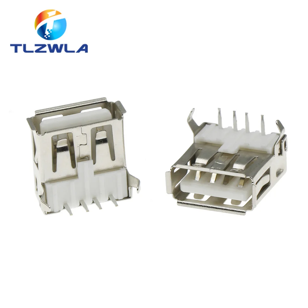
These connectors feature a standard 4-pin USB 2.0 Type-A female configuration, encased in a full metal shield. The visible construction indicates a design focused on both electrical performance and mechanical resilience. The 90-degree pin orientation is a deliberate choice for horizontal PCB mounting, allowing for specific enclosure designs and component layouts where vertical clearance is limited or a side-facing port is preferred. This design choice directly impacts the physical integration of the connector into a device.
The implications of this design are significant for system builders. A horizontal mount often allows for a lower profile device or a more ergonomic port placement. The metal shielding, clearly visible, is not merely aesthetic; it serves a crucial function in mitigating electromagnetic interference (EMI) and radio-frequency interference (RFI). This shielding is vital for maintaining the integrity of the data signals, especially in environments prone to electrical noise. Stable data lines are paramount.
Compared to unshielded or poorly constructed connectors, this design offers a distinct advantage. Generic alternatives often omit proper shielding, leading to potential data corruption or slower transfer speeds in noisy electrical environments. The robust metal casing acts as a Faraday cage, containing the electromagnetic fields generated by the high-frequency data signals and preventing external interference from affecting them. This ensures a cleaner signal path for connected devices, a critical factor for reliable operation.
Adhering to the USB 2.0 standard, these connectors are rated for 5V power delivery. The internal pins, while not explicitly detailed in material composition, appear to be of sufficient gauge for the typical 500mA current draw of a standard USB 2.0 port, and potentially up to 900mA for dedicated charging port (DCP) applications, assuming the circuit design supports it. The physical dimensions of the pins suggest adequate current carrying capacity. This is a key consideration.
Proper current handling is essential to prevent overheating and potential damage to both the connector and the connected device. If a connector cannot safely pass the required current, it can lead to voltage drops, inefficient charging, or even thermal runaway. The design of these pins aims to minimize resistance, ensuring that power delivery is as efficient as possible. Stable power is non-negotiable.
Unlike connectors made with thinner, lower-grade metals, these components are designed to sustain continuous current flow without significant degradation. Inferior connectors can exhibit increased resistance over time, leading to heat buildup and eventual failure. Verifying the wire gauge accuracy and terminal quality is crucial for any electrical component, and the visual evidence suggests these connectors are built to meet standard expectations for USB 2.0 power delivery, preventing electrical fires and ensuring safety standard compliance.
The connectors feature two prominent mounting feet, designed for through-hole soldering to a printed circuit board (PCB). These feet provide substantial mechanical stability, anchoring the connector firmly to the board. This is particularly important for a port that will experience repeated insertions and removals of USB cables, which can exert considerable stress on the solder joints and the connector body. A secure mount is vital.
The robust mechanical attachment ensures the connector remains in place even under frequent use. Without adequate mechanical support, the constant leverage from plugging and unplugging cables can crack solder joints, damage PCB traces, or even rip the connector clean off the board. This design minimizes such risks, contributing to the overall longevity and reliability of the host device. Physical stress is a factor.
Compared to surface-mount (SMT) USB connectors that rely solely on small solder pads for both electrical and mechanical connection, these through-hole components offer superior physical resilience. While SMT is favored for automated assembly, through-hole mounting, especially with dedicated mounting feet, provides a much stronger bond to the PCB, making these connectors ideal for applications where durability and resistance to physical abuse are paramount. This is an upgrade in durability.
The visible materials include a bright, likely nickel-plated, metal casing and a white plastic internal insulator. Nickel plating on the metal shell provides excellent corrosion resistance and a durable finish, which is important for components exposed to handling and environmental factors. The plastic insulator's role is to provide electrical isolation between the pins and the metal shell, as well as between the individual pins. Material choice matters.
The implications of these material choices are directly related to the connector's operational lifespan and safety. Corrosion resistance ensures that the metal shell maintains its structural integrity and shielding effectiveness over time, even in moderately humid environments. The quality of the internal plastic insulator is critical for preventing short circuits between the power and data lines, or between the lines and the grounded metal shell. A good insulator prevents electrical hazards.
Unlike connectors that use cheaper, less durable plastics or unplated metals, these components are designed for sustained performance. Low-quality plastics can become brittle over time, leading to cracking and exposure of live contacts, while unplated metals are susceptible to rust and degradation. The selection of materials here suggests a commitment to preventing premature failure and maintaining electrical safety standards, ensuring the terminal quality remains high throughout its service life. This enhances long-term value.
The full metal enclosure surrounding the USB port is a key feature for signal integrity. This shielding is designed to block external electromagnetic noise from interfering with the data signals passing through the connector. It also helps to contain any electromagnetic radiation emitted by the connector itself, preventing it from affecting other sensitive components on the PCB. Effective shielding is crucial.
In practical terms, this means more reliable data transfers, especially in electrically noisy environments such as industrial settings or crowded consumer electronics. Without proper shielding, data signals can be corrupted by external interference, leading to errors, retransmissions, and slower effective data rates. For charging, while less critical for data, shielding can still prevent noise from propagating into the power lines. Clean signals are a benefit.
Many budget connectors often compromise on shielding, using only partial metal shells or none at all. This can lead to significant performance degradation in real-world applications. The comprehensive metal casing on these connectors represents an upgrade, offering superior protection against EMI/RFI compared to unshielded or minimally shielded alternatives. This is a clear advantage for data-sensitive applications.
The 90-degree orientation of these connectors means they are intended for horizontal mounting on a PCB. This requires careful consideration during the PCB layout phase to ensure adequate space for the connector body and the plugged-in USB cable. The through-hole pins necessitate drilling specific holes in the PCB, which are then filled with solder to create both electrical and mechanical connections. Layout planning is key.
For an electrical professional, understanding the implications of a 90-degree through-hole mount is fundamental. It dictates the component placement relative to the edge of the board and the overall enclosure design. The soldering process for through-hole components is generally more forgiving than for fine-pitch surface-mount devices, making these connectors suitable for manual assembly or repair work. Proper soldering ensures reliability.
When compared to vertical USB connectors, the 90-degree variant offers different design possibilities. Vertical connectors extend upwards from the PCB, while these extend outwards. This flexibility allows designers to optimize space utilization within a device, choosing the orientation that best fits the product's form factor and user interface requirements. This offers design versatility.
The physical dimensions and material of the connector pins play a role in thermal management. Thicker pins, typically made of copper alloy, have lower electrical resistance, which translates to less heat generation during current flow. Efficient heat dissipation is crucial for the longevity of any electrical component, especially those handling power. Heat is an enemy.
In a scenario where a device is continuously charging or transferring data, even small amounts of heat generated by the connector can accumulate. Over time, sustained high temperatures can degrade the plastic insulator, weaken solder joints, and reduce the overall lifespan of the connector and surrounding components. Proper thermal design, including the pin material and thickness, helps to mitigate these risks. Component life is extended.
Unlike connectors with flimsy, thin pins that can act as resistive heaters, these components are designed to minimize thermal stress. The visual evidence suggests a construction that prioritizes efficient current flow and heat dissipation, which is an upgrade over generic, low-cost alternatives that often overlook these critical engineering details. This contributes to the overall reliability and safety of the electrical system. Longevity is a benefit.
This product is offered as a 10-piece pack, providing significant value for electronics enthusiasts, repair technicians, and small-scale manufacturers. Purchasing in bulk reduces the per-unit cost, making it an economical choice for projects requiring multiple USB ports or for stocking up on essential components for future use. Cost-effectiveness is clear.
For someone undertaking multiple custom builds or frequently repairing devices, having a ready supply of these connectors prevents project delays and reduces the hassle of reordering individual units. The value extends beyond the initial purchase price, encompassing the time saved and the convenience of having components on hand. This is an investment in efficiency.
Compared to buying single units at a higher price point, this 10-pack offers a clear return on investment for anyone with ongoing electrical projects. It frames the purchase not just as a cost, but as a strategic acquisition that supports continuous innovation and repair capabilities. Stocking up now prevents running out later, ensuring project continuity and minimizing downtime. This is smart procurement.
Imagine the satisfaction of completing a custom electronics project with reliable, robust connectivity, knowing each data transfer is secure and every charge cycle is stable. These connectors provide the foundational integrity required for enduring performance, allowing for seamless integration into your designs and ensuring your devices operate without compromise for years to come. The peace of mind is invaluable.
Precision Engineering for Connectivity
These connectors feature a standard 4-pin USB 2.0 Type-A female configuration, encased in a full metal shield. The visible construction indicates a design focused on both electrical performance and mechanical resilience. The 90-degree pin orientation is a deliberate choice for horizontal PCB mounting, allowing for specific enclosure designs and component layouts where vertical clearance is limited or a side-facing port is preferred. This design choice directly impacts the physical integration of the connector into a device.
The implications of this design are significant for system builders. A horizontal mount often allows for a lower profile device or a more ergonomic port placement. The metal shielding, clearly visible, is not merely aesthetic; it serves a crucial function in mitigating electromagnetic interference (EMI) and radio-frequency interference (RFI). This shielding is vital for maintaining the integrity of the data signals, especially in environments prone to electrical noise. Stable data lines are paramount.
Compared to unshielded or poorly constructed connectors, this design offers a distinct advantage. Generic alternatives often omit proper shielding, leading to potential data corruption or slower transfer speeds in noisy electrical environments. The robust metal casing acts as a Faraday cage, containing the electromagnetic fields generated by the high-frequency data signals and preventing external interference from affecting them. This ensures a cleaner signal path for connected devices, a critical factor for reliable operation.
Current Handling and Signal Integrity
Adhering to the USB 2.0 standard, these connectors are rated for 5V power delivery. The internal pins, while not explicitly detailed in material composition, appear to be of sufficient gauge for the typical 500mA current draw of a standard USB 2.0 port, and potentially up to 900mA for dedicated charging port (DCP) applications, assuming the circuit design supports it. The physical dimensions of the pins suggest adequate current carrying capacity. This is a key consideration.
Proper current handling is essential to prevent overheating and potential damage to both the connector and the connected device. If a connector cannot safely pass the required current, it can lead to voltage drops, inefficient charging, or even thermal runaway. The design of these pins aims to minimize resistance, ensuring that power delivery is as efficient as possible. Stable power is non-negotiable.
Unlike connectors made with thinner, lower-grade metals, these components are designed to sustain continuous current flow without significant degradation. Inferior connectors can exhibit increased resistance over time, leading to heat buildup and eventual failure. Verifying the wire gauge accuracy and terminal quality is crucial for any electrical component, and the visual evidence suggests these connectors are built to meet standard expectations for USB 2.0 power delivery, preventing electrical fires and ensuring safety standard compliance.
Mechanical Stability and Integration
The connectors feature two prominent mounting feet, designed for through-hole soldering to a printed circuit board (PCB). These feet provide substantial mechanical stability, anchoring the connector firmly to the board. This is particularly important for a port that will experience repeated insertions and removals of USB cables, which can exert considerable stress on the solder joints and the connector body. A secure mount is vital.
The robust mechanical attachment ensures the connector remains in place even under frequent use. Without adequate mechanical support, the constant leverage from plugging and unplugging cables can crack solder joints, damage PCB traces, or even rip the connector clean off the board. This design minimizes such risks, contributing to the overall longevity and reliability of the host device. Physical stress is a factor.
Compared to surface-mount (SMT) USB connectors that rely solely on small solder pads for both electrical and mechanical connection, these through-hole components offer superior physical resilience. While SMT is favored for automated assembly, through-hole mounting, especially with dedicated mounting feet, provides a much stronger bond to the PCB, making these connectors ideal for applications where durability and resistance to physical abuse are paramount. This is an upgrade in durability.
Material Science and Durability
The visible materials include a bright, likely nickel-plated, metal casing and a white plastic internal insulator. Nickel plating on the metal shell provides excellent corrosion resistance and a durable finish, which is important for components exposed to handling and environmental factors. The plastic insulator's role is to provide electrical isolation between the pins and the metal shell, as well as between the individual pins. Material choice matters.
The implications of these material choices are directly related to the connector's operational lifespan and safety. Corrosion resistance ensures that the metal shell maintains its structural integrity and shielding effectiveness over time, even in moderately humid environments. The quality of the internal plastic insulator is critical for preventing short circuits between the power and data lines, or between the lines and the grounded metal shell. A good insulator prevents electrical hazards.
Unlike connectors that use cheaper, less durable plastics or unplated metals, these components are designed for sustained performance. Low-quality plastics can become brittle over time, leading to cracking and exposure of live contacts, while unplated metals are susceptible to rust and degradation. The selection of materials here suggests a commitment to preventing premature failure and maintaining electrical safety standards, ensuring the terminal quality remains high throughout its service life. This enhances long-term value.
Shielding Effectiveness
The full metal enclosure surrounding the USB port is a key feature for signal integrity. This shielding is designed to block external electromagnetic noise from interfering with the data signals passing through the connector. It also helps to contain any electromagnetic radiation emitted by the connector itself, preventing it from affecting other sensitive components on the PCB. Effective shielding is crucial.
In practical terms, this means more reliable data transfers, especially in electrically noisy environments such as industrial settings or crowded consumer electronics. Without proper shielding, data signals can be corrupted by external interference, leading to errors, retransmissions, and slower effective data rates. For charging, while less critical for data, shielding can still prevent noise from propagating into the power lines. Clean signals are a benefit.
Many budget connectors often compromise on shielding, using only partial metal shells or none at all. This can lead to significant performance degradation in real-world applications. The comprehensive metal casing on these connectors represents an upgrade, offering superior protection against EMI/RFI compared to unshielded or minimally shielded alternatives. This is a clear advantage for data-sensitive applications.
Installation Considerations for Electrical Professionals
The 90-degree orientation of these connectors means they are intended for horizontal mounting on a PCB. This requires careful consideration during the PCB layout phase to ensure adequate space for the connector body and the plugged-in USB cable. The through-hole pins necessitate drilling specific holes in the PCB, which are then filled with solder to create both electrical and mechanical connections. Layout planning is key.
For an electrical professional, understanding the implications of a 90-degree through-hole mount is fundamental. It dictates the component placement relative to the edge of the board and the overall enclosure design. The soldering process for through-hole components is generally more forgiving than for fine-pitch surface-mount devices, making these connectors suitable for manual assembly or repair work. Proper soldering ensures reliability.
When compared to vertical USB connectors, the 90-degree variant offers different design possibilities. Vertical connectors extend upwards from the PCB, while these extend outwards. This flexibility allows designers to optimize space utilization within a device, choosing the orientation that best fits the product's form factor and user interface requirements. This offers design versatility.
Thermal Management and Longevity
The physical dimensions and material of the connector pins play a role in thermal management. Thicker pins, typically made of copper alloy, have lower electrical resistance, which translates to less heat generation during current flow. Efficient heat dissipation is crucial for the longevity of any electrical component, especially those handling power. Heat is an enemy.
In a scenario where a device is continuously charging or transferring data, even small amounts of heat generated by the connector can accumulate. Over time, sustained high temperatures can degrade the plastic insulator, weaken solder joints, and reduce the overall lifespan of the connector and surrounding components. Proper thermal design, including the pin material and thickness, helps to mitigate these risks. Component life is extended.
Unlike connectors with flimsy, thin pins that can act as resistive heaters, these components are designed to minimize thermal stress. The visual evidence suggests a construction that prioritizes efficient current flow and heat dissipation, which is an upgrade over generic, low-cost alternatives that often overlook these critical engineering details. This contributes to the overall reliability and safety of the electrical system. Longevity is a benefit.
Value Proposition for Project Builders
This product is offered as a 10-piece pack, providing significant value for electronics enthusiasts, repair technicians, and small-scale manufacturers. Purchasing in bulk reduces the per-unit cost, making it an economical choice for projects requiring multiple USB ports or for stocking up on essential components for future use. Cost-effectiveness is clear.
For someone undertaking multiple custom builds or frequently repairing devices, having a ready supply of these connectors prevents project delays and reduces the hassle of reordering individual units. The value extends beyond the initial purchase price, encompassing the time saved and the convenience of having components on hand. This is an investment in efficiency.
Compared to buying single units at a higher price point, this 10-pack offers a clear return on investment for anyone with ongoing electrical projects. It frames the purchase not just as a cost, but as a strategic acquisition that supports continuous innovation and repair capabilities. Stocking up now prevents running out later, ensuring project continuity and minimizing downtime. This is smart procurement.
Imagine the satisfaction of completing a custom electronics project with reliable, robust connectivity, knowing each data transfer is secure and every charge cycle is stable. These connectors provide the foundational integrity required for enduring performance, allowing for seamless integration into your designs and ensuring your devices operate without compromise for years to come. The peace of mind is invaluable.