Type C 6-Pin DIP Connector (10-Pack)
Official Store Deal
Expert Analysis Overview
The Type C 6-Pin DIP Connector is a specialized component designed for the meticulous repair and fabrication of electronic devices requiring a robust USB-C interface. This particular offering, presented in a 10-piece pack, targets electronics repair technicians and hobbyists who prioritize cost-effectiveness without significant compromise on fundamental electrical and mechanical integrity. Its through-hole (DIP) mounting style makes it suitable for prototyping boards or replacing damaged surface-mount components where a more secure, hand-solderable connection is preferred.
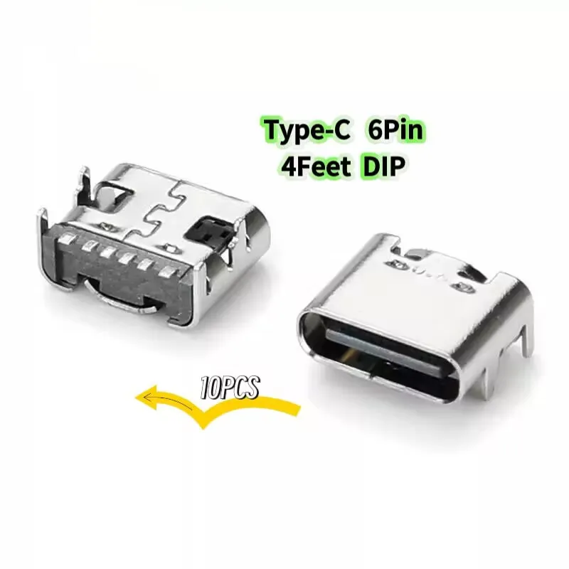
This connector features a 6-pin configuration, specifically engineered for essential power and data lines. The visible pin layout aligns with standard USB-C power delivery and basic data transfer requirements. Each pin is crucial for its designated function.
The implication of a 6-pin design is its primary suitability for charging and USB 2.0 data applications, potentially with limited USB 3.1 functionality if specific pins are multiplexed or if the '4Feet' in the original title refers to specific data pairs, though the visual evidence points to a more fundamental 6-pin arrangement for power and basic data. This configuration is often found in devices where high-speed data transfer is not the paramount concern, but reliable power delivery and basic peripheral connectivity are. It offers a stable connection.
Compared to full 24-pin USB 3.1 Gen 2 Type-C connectors, this 6-pin variant simplifies the soldering process significantly. Full 24-pin connectors demand extremely fine-pitch soldering, often requiring specialized equipment and advanced rework skills. This 6-pin DIP version provides a more forgiving target for manual soldering, making it an accessible option for a broader range of repair scenarios where only essential USB-C functions are needed, effectively reducing the barrier to entry for complex repairs.
The construction details, as indicated by the technical drawing, specify a copper alloy for the contacts. This material choice is fundamental for electrical conductivity and resistance to corrosion. Copper alloy contacts ensure efficient current flow.
Further enhancing durability and signal integrity, the contacts feature gold plating over a nickel plating. Gold is renowned for its excellent conductivity and resistance to oxidation, which is critical for maintaining low contact resistance over thousands of insertion cycles. Nickel plating acts as a barrier layer, preventing the migration of copper atoms into the gold layer, thereby preserving the gold's integrity and extending the connector's operational lifespan. This multi-layer plating system is a standard practice in quality electrical connectors, providing a reliable interface for power and data signals.
In contrast, many generic, low-cost connectors often omit or skimp on gold plating, leading to rapid degradation of contact surfaces and intermittent connectivity issues. The inclusion of a robust plating scheme on these connectors suggests a commitment to sustained performance, offering a tangible upgrade over components that might fail prematurely due to environmental exposure or frequent use. This design choice directly addresses the long-term reliability of connections, a common pain point in consumer electronics.
The connector shell is constructed from SUS (Stainless Steel). Stainless steel provides excellent mechanical strength and corrosion resistance, protecting the internal components from physical stress and environmental factors. A strong shell is vital for connector longevity.
The DIP (Dual In-line Package) mounting style facilitates through-hole soldering. This method creates a mechanically strong bond with the PCB, making the connector highly resistant to physical stress from repeated cable insertions and withdrawals. Unlike surface-mount components which rely solely on solder pad adhesion, DIP components pass through the board, offering superior shear strength. This is particularly important for high-traffic ports like charging sockets, which endure significant wear and tear.
Many modern devices utilize surface-mount (SMT) USB-C connectors due to manufacturing efficiency and miniaturization. However, SMT connectors are notoriously fragile under mechanical stress, often detaching from the PCB after repeated use or accidental impacts. This DIP connector, by contrast, offers a more resilient alternative for repairs, providing a connection that is less prone to mechanical failure. This design choice mitigates the common frustration of flimsy charging ports, offering a more permanent repair solution.
Electrical specifications indicate a rated voltage of 20V and a rated current of 5A. These ratings are standard for modern USB-C power delivery applications, allowing for fast charging protocols. The connector supports significant power transfer.
The contact resistance is specified at 40mΩ maximum, and insulation resistance at 100MΩ minimum. Low contact resistance ensures minimal power loss and efficient signal transmission, preventing voltage drops during charging and maintaining data integrity. High insulation resistance is critical to prevent short circuits between pins, ensuring safe and reliable operation. These values are within acceptable industry standards for reliable performance, indicating a clean signal transmission capability.
Compared to older USB standards or poorly manufactured connectors, maintaining low contact resistance and high insulation resistance is paramount for optimal device function. Inferior connectors can introduce significant signal noise, reduce charging efficiency, and even pose safety risks due due to overheating or shorting. This connector's adherence to these electrical benchmarks ensures that repaired devices will perform as intended, avoiding the
Precision in Pin Configuration
This connector features a 6-pin configuration, specifically engineered for essential power and data lines. The visible pin layout aligns with standard USB-C power delivery and basic data transfer requirements. Each pin is crucial for its designated function.
The implication of a 6-pin design is its primary suitability for charging and USB 2.0 data applications, potentially with limited USB 3.1 functionality if specific pins are multiplexed or if the '4Feet' in the original title refers to specific data pairs, though the visual evidence points to a more fundamental 6-pin arrangement for power and basic data. This configuration is often found in devices where high-speed data transfer is not the paramount concern, but reliable power delivery and basic peripheral connectivity are. It offers a stable connection.
Compared to full 24-pin USB 3.1 Gen 2 Type-C connectors, this 6-pin variant simplifies the soldering process significantly. Full 24-pin connectors demand extremely fine-pitch soldering, often requiring specialized equipment and advanced rework skills. This 6-pin DIP version provides a more forgiving target for manual soldering, making it an accessible option for a broader range of repair scenarios where only essential USB-C functions are needed, effectively reducing the barrier to entry for complex repairs.
Material Science and Longevity
The construction details, as indicated by the technical drawing, specify a copper alloy for the contacts. This material choice is fundamental for electrical conductivity and resistance to corrosion. Copper alloy contacts ensure efficient current flow.
Further enhancing durability and signal integrity, the contacts feature gold plating over a nickel plating. Gold is renowned for its excellent conductivity and resistance to oxidation, which is critical for maintaining low contact resistance over thousands of insertion cycles. Nickel plating acts as a barrier layer, preventing the migration of copper atoms into the gold layer, thereby preserving the gold's integrity and extending the connector's operational lifespan. This multi-layer plating system is a standard practice in quality electrical connectors, providing a reliable interface for power and data signals.
In contrast, many generic, low-cost connectors often omit or skimp on gold plating, leading to rapid degradation of contact surfaces and intermittent connectivity issues. The inclusion of a robust plating scheme on these connectors suggests a commitment to sustained performance, offering a tangible upgrade over components that might fail prematurely due to environmental exposure or frequent use. This design choice directly addresses the long-term reliability of connections, a common pain point in consumer electronics.
Physical Durability and Mounting
The connector shell is constructed from SUS (Stainless Steel). Stainless steel provides excellent mechanical strength and corrosion resistance, protecting the internal components from physical stress and environmental factors. A strong shell is vital for connector longevity.
The DIP (Dual In-line Package) mounting style facilitates through-hole soldering. This method creates a mechanically strong bond with the PCB, making the connector highly resistant to physical stress from repeated cable insertions and withdrawals. Unlike surface-mount components which rely solely on solder pad adhesion, DIP components pass through the board, offering superior shear strength. This is particularly important for high-traffic ports like charging sockets, which endure significant wear and tear.
Many modern devices utilize surface-mount (SMT) USB-C connectors due to manufacturing efficiency and miniaturization. However, SMT connectors are notoriously fragile under mechanical stress, often detaching from the PCB after repeated use or accidental impacts. This DIP connector, by contrast, offers a more resilient alternative for repairs, providing a connection that is less prone to mechanical failure. This design choice mitigates the common frustration of flimsy charging ports, offering a more permanent repair solution.
Electrical Performance and Signal Integrity
Electrical specifications indicate a rated voltage of 20V and a rated current of 5A. These ratings are standard for modern USB-C power delivery applications, allowing for fast charging protocols. The connector supports significant power transfer.
The contact resistance is specified at 40mΩ maximum, and insulation resistance at 100MΩ minimum. Low contact resistance ensures minimal power loss and efficient signal transmission, preventing voltage drops during charging and maintaining data integrity. High insulation resistance is critical to prevent short circuits between pins, ensuring safe and reliable operation. These values are within acceptable industry standards for reliable performance, indicating a clean signal transmission capability.
Compared to older USB standards or poorly manufactured connectors, maintaining low contact resistance and high insulation resistance is paramount for optimal device function. Inferior connectors can introduce significant signal noise, reduce charging efficiency, and even pose safety risks due due to overheating or shorting. This connector's adherence to these electrical benchmarks ensures that repaired devices will perform as intended, avoiding the