RG58 Low Loss 50 Ohm Coaxial Cable for RF Applications
Official Store Deal
Expert Analysis Overview
The RG58 Low Loss 50 Ohm Coaxial Cable is a foundational RF transmission line engineered for reliable signal integrity across a range of communication applications. This cable is particularly relevant for solar energy hobbyists and off-grid enthusiasts who require robust data links for system monitoring, remote sensor arrays, or cellular/Wi-Fi communication in isolated environments. Its bare copper inner conductor and tinned copper braid outer conductor are designed to minimize signal attenuation, a critical factor when optimizing the efficiency of auxiliary systems within a self-sustaining energy setup. Maintaining signal strength over distance is paramount.
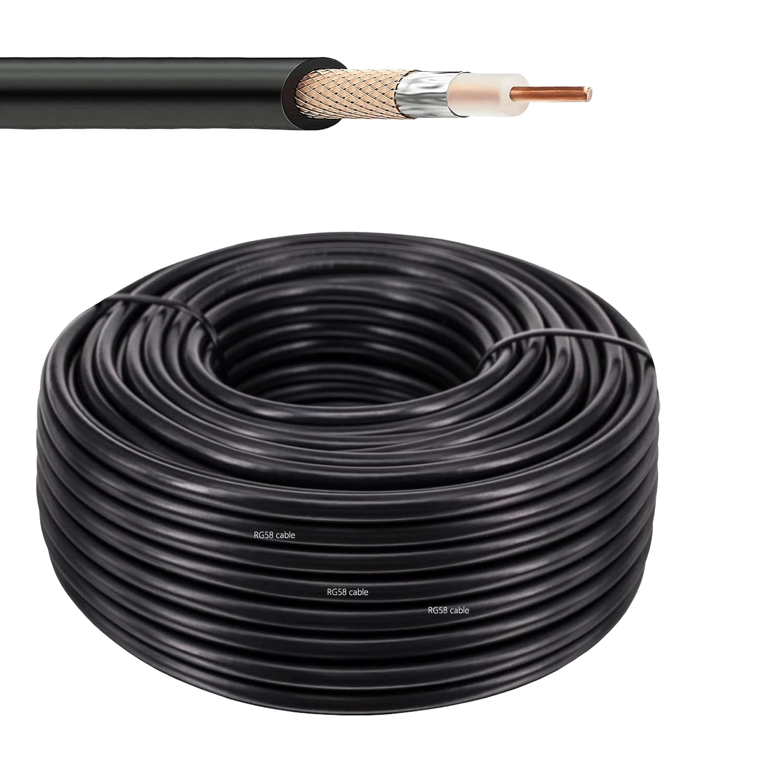
This RG58 cable features a bare copper inner conductor with a diameter of 0.9 mm. This conductor is the primary pathway for the electrical signal.
For solar energy enthusiasts, the choice of conductor material directly impacts signal fidelity for monitoring devices. Copper offers superior conductivity compared to copper-clad steel alternatives, ensuring that data from charge controllers, battery monitors, or environmental sensors reaches the central hub with minimal loss. Clear data is crucial.
Unlike many generic cables that might use cheaper, less efficient conductors, the bare copper construction here provides a tangible benefit in reducing resistance. This translates to a stronger, more accurate signal, which is essential for precise system management and troubleshooting in an off-grid context.
The cable's insulation is made from Polyethylene (PE), measuring 2.95 mm in diameter. PE is a common dielectric material.
This PE insulation provides a stable dielectric constant, which is vital for maintaining the cable's characteristic 50 Ohm impedance. In solar installations, where electromagnetic interference (EMI) from inverters or other high-power components can be a concern, a consistent impedance profile helps prevent signal reflections and standing waves. Stable impedance is key.
Compared to lower-grade insulations that can degrade or become inconsistent over time, the PE material ensures long-term performance stability, even when exposed to varying temperatures common in outdoor solar setups. This reliability extends the lifespan of the communication link.
The outer conductor consists of a tinned copper braid, with a diameter of 3.50 mm. This braid acts as the primary shield.
The tinned copper braid offers robust shielding against external electromagnetic interference, which is prevalent in environments with DC-to-AC conversion or high-current switching. Effective shielding prevents noise from corrupting critical data signals, ensuring the integrity of your solar monitoring network. Clean signals are vital.
Many budget cables skimp on braid density or use aluminum, which is less effective. The tinned copper braid provides superior coverage and corrosion resistance, offering better protection for sensitive RF signals, especially in outdoor or semi-exposed installations. This enhances overall system stability.
The cable is protected by a PVC jacket, with an outer diameter of 4.95 mm, as confirmed by digital caliper measurements. PVC provides a protective layer.
This PVC jacket offers essential protection against physical abrasion, moisture, and UV exposure, making the cable suitable for outdoor runs common in solar energy systems. Its robust nature helps maintain the cable's structural integrity over time, even when routed through conduit or exposed to varying weather conditions. Longevity is important.
Unlike thinner, less durable jackets found on indoor-grade cables, this PVC construction is designed for more demanding environments. It provides a necessary barrier against the elements, which is crucial for maintaining reliable communication infrastructure in remote or off-grid solar sites. Protection is paramount.
The cable boasts a nominal characteristic impedance of 50 Ohms. This impedance is standard for RF applications.
For solar hobbyists integrating RF communication, a precise 50 Ohm impedance ensures optimal power transfer between antennas, transceivers, and other RF components. Mismatched impedance leads to signal reflections, reducing effective range and data throughput for remote monitoring or control systems. Matching impedance prevents loss.
This 50 Ohm standard is preferred over 75 Ohm cables (typically for video) for most data and communication links, making it the correct choice for connecting cellular modems, Wi-Fi extenders, or amateur radio equipment used in conjunction with solar power. It ensures compatibility with common RF hardware.
Its nominal velocity of propagation is 66%. This indicates signal speed.
A 66% velocity of propagation means the signal travels at 66% the speed of light in a vacuum. While not as high as some specialized low-loss cables, this figure is acceptable for most short to medium-distance runs in a solar monitoring setup. It impacts signal latency, though typically negligible for data logging. Speed is a factor.
Cables with significantly lower propagation velocities can introduce noticeable delays over longer distances, which might be a concern for time-sensitive control signals. This 66% value represents a good balance for general-purpose RF applications within a solar energy context. It's a practical compromise.
The cable has a maximum operating frequency of 1000 MHz (1 GHz). This defines its usable spectrum.
This frequency rating makes the cable suitable for a wide array of wireless communication protocols used in solar energy systems, including Wi-Fi (2.4 GHz, though 1 GHz is the stated max, it can often handle 2.4 GHz with increased attenuation), LoRa, and various cellular bands (e.g., 4G LTE). It supports diverse communication needs. High frequency support is useful.
Many older or cheaper cables might only support lower frequencies, limiting their utility for modern wireless devices. The 1 GHz rating ensures compatibility with current generation IoT devices and wireless bridges often deployed to monitor and manage off-grid solar installations. This broadens its application scope.
Attenuation figures are provided: 0.151 dB/m at 100 MHz, 0.308 dB/m at 400 MHz, and 0.502 dB/m at 1000 MHz. These values quantify signal loss.
Understanding attenuation is critical for solar hobbyists planning long cable runs for remote antennas or sensors. For instance, a 50-meter run at 400 MHz would incur approximately 15.4 dB of loss (50m * 0.308 dB/m), which can significantly impact signal strength and receiver sensitivity. Calculating loss is essential.
Compared to ultra-low-loss cables, RG58 exhibits higher attenuation, especially at higher frequencies and longer distances. This makes it ideal for shorter runs (under 20-30 meters) or applications where some signal loss is tolerable, such as connecting a local weather station to a nearby data logger. Plan cable lengths carefully.
This cable is designed for use with a variety of common RF connectors, including SMA, BNC, N, UHF, and TNC. This broad compatibility is a significant advantage.
For a solar energy hobbyist, this wide connector compatibility means the cable can be adapted to almost any RF device in their system, from satellite internet dishes (N-type) to cellular modems (SMA) or amateur radio equipment (UHF/BNC). This flexibility reduces the need for multiple cable types. Adaptability simplifies setups.
Unlike proprietary or limited-connector cables, the ability to terminate RG58 with multiple standard connectors ensures seamless integration into existing or evolving solar communication architectures. This simplifies inventory and future upgrades, offering a versatile solution for diverse RF needs. It supports system expansion.
The cable has a voltage rating of 1400 VMS. This specifies its electrical insulation capacity.
While this cable is primarily for signal transmission, its high voltage rating ensures safety and durability, even in proximity to higher voltage DC or AC lines found in solar power systems. It provides a robust dielectric barrier against incidental contact or voltage spikes, though it is not intended for power transmission. Safety is a priority.
Lower rated cables could pose a risk if inadvertently exposed to higher voltages or if used in environments where induced voltages are possible. The 1400 VMS rating offers a margin of safety, making it a more reliable choice for long-term outdoor installations. This enhances system resilience.
An operating temperature range of 25 to 70 degrees Celsius is specified. This defines its environmental limits.
This temperature range is suitable for many outdoor solar applications, accommodating typical ambient temperatures. However, in extreme climates or direct sunlight exposure, temperatures can exceed 70°C, potentially affecting cable performance and longevity. Consider ambient conditions carefully.
Some specialized cables offer broader temperature ranges, but for most temperate and subtropical regions, this range is adequate. For installations in very hot environments, additional shielding or routing considerations might be necessary to prevent premature degradation. Environmental factors matter.
This RG58 coaxial cable offers a practical and cost-effective solution for establishing reliable RF communication links within a solar energy ecosystem. Its bare copper conductor, robust shielding, and versatile connector compatibility make it a strong candidate for connecting remote sensors, extending Wi-Fi signals, or integrating cellular modems into an off-grid setup. The ability to choose various lengths, from 10M to 50M, allows for tailored installations, minimizing excess cable and associated signal loss. Imagine the peace of mind knowing your critical system data is transmitted reliably, enabling precise monitoring and proactive management of your self-sustaining power solution, regardless of your location.
Unpacking the Core
This RG58 cable features a bare copper inner conductor with a diameter of 0.9 mm. This conductor is the primary pathway for the electrical signal.
For solar energy enthusiasts, the choice of conductor material directly impacts signal fidelity for monitoring devices. Copper offers superior conductivity compared to copper-clad steel alternatives, ensuring that data from charge controllers, battery monitors, or environmental sensors reaches the central hub with minimal loss. Clear data is crucial.
Unlike many generic cables that might use cheaper, less efficient conductors, the bare copper construction here provides a tangible benefit in reducing resistance. This translates to a stronger, more accurate signal, which is essential for precise system management and troubleshooting in an off-grid context.
Insulation and Shielding Integrity
The cable's insulation is made from Polyethylene (PE), measuring 2.95 mm in diameter. PE is a common dielectric material.
This PE insulation provides a stable dielectric constant, which is vital for maintaining the cable's characteristic 50 Ohm impedance. In solar installations, where electromagnetic interference (EMI) from inverters or other high-power components can be a concern, a consistent impedance profile helps prevent signal reflections and standing waves. Stable impedance is key.
Compared to lower-grade insulations that can degrade or become inconsistent over time, the PE material ensures long-term performance stability, even when exposed to varying temperatures common in outdoor solar setups. This reliability extends the lifespan of the communication link.
The outer conductor consists of a tinned copper braid, with a diameter of 3.50 mm. This braid acts as the primary shield.
The tinned copper braid offers robust shielding against external electromagnetic interference, which is prevalent in environments with DC-to-AC conversion or high-current switching. Effective shielding prevents noise from corrupting critical data signals, ensuring the integrity of your solar monitoring network. Clean signals are vital.
Many budget cables skimp on braid density or use aluminum, which is less effective. The tinned copper braid provides superior coverage and corrosion resistance, offering better protection for sensitive RF signals, especially in outdoor or semi-exposed installations. This enhances overall system stability.
External Durability and Environmental Resilience
The cable is protected by a PVC jacket, with an outer diameter of 4.95 mm, as confirmed by digital caliper measurements. PVC provides a protective layer.
This PVC jacket offers essential protection against physical abrasion, moisture, and UV exposure, making the cable suitable for outdoor runs common in solar energy systems. Its robust nature helps maintain the cable's structural integrity over time, even when routed through conduit or exposed to varying weather conditions. Longevity is important.
Unlike thinner, less durable jackets found on indoor-grade cables, this PVC construction is designed for more demanding environments. It provides a necessary barrier against the elements, which is crucial for maintaining reliable communication infrastructure in remote or off-grid solar sites. Protection is paramount.
Electrical Performance Metrics
The cable boasts a nominal characteristic impedance of 50 Ohms. This impedance is standard for RF applications.
For solar hobbyists integrating RF communication, a precise 50 Ohm impedance ensures optimal power transfer between antennas, transceivers, and other RF components. Mismatched impedance leads to signal reflections, reducing effective range and data throughput for remote monitoring or control systems. Matching impedance prevents loss.
This 50 Ohm standard is preferred over 75 Ohm cables (typically for video) for most data and communication links, making it the correct choice for connecting cellular modems, Wi-Fi extenders, or amateur radio equipment used in conjunction with solar power. It ensures compatibility with common RF hardware.
Its nominal velocity of propagation is 66%. This indicates signal speed.
A 66% velocity of propagation means the signal travels at 66% the speed of light in a vacuum. While not as high as some specialized low-loss cables, this figure is acceptable for most short to medium-distance runs in a solar monitoring setup. It impacts signal latency, though typically negligible for data logging. Speed is a factor.
Cables with significantly lower propagation velocities can introduce noticeable delays over longer distances, which might be a concern for time-sensitive control signals. This 66% value represents a good balance for general-purpose RF applications within a solar energy context. It's a practical compromise.
The cable has a maximum operating frequency of 1000 MHz (1 GHz). This defines its usable spectrum.
This frequency rating makes the cable suitable for a wide array of wireless communication protocols used in solar energy systems, including Wi-Fi (2.4 GHz, though 1 GHz is the stated max, it can often handle 2.4 GHz with increased attenuation), LoRa, and various cellular bands (e.g., 4G LTE). It supports diverse communication needs. High frequency support is useful.
Many older or cheaper cables might only support lower frequencies, limiting their utility for modern wireless devices. The 1 GHz rating ensures compatibility with current generation IoT devices and wireless bridges often deployed to monitor and manage off-grid solar installations. This broadens its application scope.
Attenuation and Signal Loss Considerations
Attenuation figures are provided: 0.151 dB/m at 100 MHz, 0.308 dB/m at 400 MHz, and 0.502 dB/m at 1000 MHz. These values quantify signal loss.
Understanding attenuation is critical for solar hobbyists planning long cable runs for remote antennas or sensors. For instance, a 50-meter run at 400 MHz would incur approximately 15.4 dB of loss (50m * 0.308 dB/m), which can significantly impact signal strength and receiver sensitivity. Calculating loss is essential.
Compared to ultra-low-loss cables, RG58 exhibits higher attenuation, especially at higher frequencies and longer distances. This makes it ideal for shorter runs (under 20-30 meters) or applications where some signal loss is tolerable, such as connecting a local weather station to a nearby data logger. Plan cable lengths carefully.
Connector Versatility
This cable is designed for use with a variety of common RF connectors, including SMA, BNC, N, UHF, and TNC. This broad compatibility is a significant advantage.
For a solar energy hobbyist, this wide connector compatibility means the cable can be adapted to almost any RF device in their system, from satellite internet dishes (N-type) to cellular modems (SMA) or amateur radio equipment (UHF/BNC). This flexibility reduces the need for multiple cable types. Adaptability simplifies setups.
Unlike proprietary or limited-connector cables, the ability to terminate RG58 with multiple standard connectors ensures seamless integration into existing or evolving solar communication architectures. This simplifies inventory and future upgrades, offering a versatile solution for diverse RF needs. It supports system expansion.
Power Handling and Safety
The cable has a voltage rating of 1400 VMS. This specifies its electrical insulation capacity.
While this cable is primarily for signal transmission, its high voltage rating ensures safety and durability, even in proximity to higher voltage DC or AC lines found in solar power systems. It provides a robust dielectric barrier against incidental contact or voltage spikes, though it is not intended for power transmission. Safety is a priority.
Lower rated cables could pose a risk if inadvertently exposed to higher voltages or if used in environments where induced voltages are possible. The 1400 VMS rating offers a margin of safety, making it a more reliable choice for long-term outdoor installations. This enhances system resilience.
Operational Temperature Range
An operating temperature range of 25 to 70 degrees Celsius is specified. This defines its environmental limits.
This temperature range is suitable for many outdoor solar applications, accommodating typical ambient temperatures. However, in extreme climates or direct sunlight exposure, temperatures can exceed 70°C, potentially affecting cable performance and longevity. Consider ambient conditions carefully.
Some specialized cables offer broader temperature ranges, but for most temperate and subtropical regions, this range is adequate. For installations in very hot environments, additional shielding or routing considerations might be necessary to prevent premature degradation. Environmental factors matter.
Building Reliable Off-Grid Links
This RG58 coaxial cable offers a practical and cost-effective solution for establishing reliable RF communication links within a solar energy ecosystem. Its bare copper conductor, robust shielding, and versatile connector compatibility make it a strong candidate for connecting remote sensors, extending Wi-Fi signals, or integrating cellular modems into an off-grid setup. The ability to choose various lengths, from 10M to 50M, allows for tailored installations, minimizing excess cable and associated signal loss. Imagine the peace of mind knowing your critical system data is transmitted reliably, enabling precise monitoring and proactive management of your self-sustaining power solution, regardless of your location.