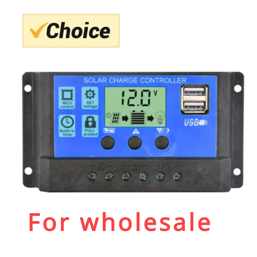
PWM Solar Charge Controller with Dual USB and LCD Display
Official Store Deal
Expert Analysis Overview
Regulating the Current Flow: Core Functionality
The PWM Solar Charge Controller is a foundational power management unit designed for entry-level off-grid solar installations requiring reliable, cost-effective battery regulation. This device serves as the critical intermediary between solar panels and battery banks, ensuring the battery receives a controlled charge while protecting it from overcharge and deep discharge. Its primary role involves maintaining battery health and extending its operational lifespan, a crucial aspect often overlooked in basic setups. The visible design emphasizes functional simplicity.The Pulse Width Modulation Mechanism
At its operational core, this controller employs Pulse Width Modulation (PWM) technology. PWM functions by rapidly switching the solar panel's connection to the battery on and off. This modulation effectively tapers the charging current as the battery approaches full capacity, preventing overcharging. The process is straightforward. Unlike more complex Maximum Power Point Tracking (MPPT) controllers, PWM technology does not convert excess voltage from the solar panel into additional current. This means that if a 20V solar panel is connected to a 12V battery, the PWM controller will essentially clip the voltage down to the battery's level, losing the "extra" voltage as heat rather than converting it into usable power. This inherent characteristic makes PWM controllers less efficient than MPPT units, particularly when the solar panel's operating voltage significantly differs from the battery's voltage, or in cooler temperatures where panels produce higher voltages. However, for systems where the solar panel's nominal voltage closely matches the battery bank's voltage (e.g., a 12V panel for a 12V battery), the efficiency difference becomes less pronounced. Simplicity is a key advantage.The design choice of PWM technology directly impacts system performance and cost. For smaller, less critical applications, the lower manufacturing cost of PWM controllers makes them an attractive option. The internal circuitry, while less complex than MPPT, still requires robust components to handle the switching currents and dissipate any generated heat. The visible heatsink, if present, would indicate thermal management considerations. Without a visible heatsink, the current rating of 10A suggests that internal components are designed for this specific load, relying on the plastic enclosure for some heat dissipation. This is a budget-friendly approach. The controller's ability to automatically detect 12V or 24V systems simplifies the installation process for users, removing a potential point of error during setup. This automatic detection relies on internal voltage sensing circuits that identify the battery's nominal voltage upon connection.
System Integration and Load Management
The controller facilitates a complete off-grid power ecosystem by providing dedicated terminals for solar panels, the battery, and DC loads. This tripartite connection ensures that power flows correctly from the source to storage and then to consumption points. Proper wiring is paramount. The clear labeling on the unit, as depicted in the system connection diagrams, guides the user through the correct sequence of connections: battery first, then solar panels, and finally the DC loads. This sequence is critical for system stability and preventing potential damage from voltage surges or incorrect initialization. The terminal blocks themselves appear to be screw-type, which necessitates careful stripping and secure tightening of wire ends to ensure low-resistance contacts. Loose connections can lead to resistive heating, power loss, and even fire hazards over time. Wire gauge selection is also important. The 10A rating implies that wiring appropriate for this current level must be used for all connections to prevent voltage drop and overheating.Beyond charging, the controller also manages the discharge of the battery to connected DC loads. This load management feature is crucial for preventing deep discharge, which can severely shorten a battery's lifespan. The adjustable timer setting, visible on the LCD interface, allows users to program when the DC loads receive power. For instance, a user could configure the controller to power outdoor lighting only from dusk till dawn, conserving battery energy during daylight hours. This programmable functionality adds a layer of intelligence to basic off-grid systems. It offers flexibility. The internal relays or MOSFETs responsible for switching the load must be rated for the specified current to ensure long-term reliability. Overloading the DC output can lead to premature component failure within the controller.
Visual Feedback and User Interface
The user interface of this solar charge controller is centered around its integrated LCD display and three tactile buttons. This combination provides the primary means for monitoring system status and configuring operational parameters. Clarity is essential. The visual information presented on the screen is critical for understanding the health and performance of the solar power system.Display Clarity and Data Presentation
The LCD screen, prominently featured on the controller's face, offers real-time data on the system's operational state. Images show a clear digital readout of the battery voltage, which is the most fundamental indicator of battery charge level. Icons representing the solar panel, battery, and load are also visible, illuminating or flashing to indicate charging, discharging, or fault conditions. This visual feedback is immediate. The display also appears to show charge and discharge current indicators, though the "Warm Tips" image clarifies that only voltage is displayed in amps or amp-hours. This distinction is important for users who might expect a full suite of current monitoring. The absence of direct current readings means users cannot precisely track energy flow without external meters. This limits diagnostic capability. For a basic controller, however, the voltage readout and status icons provide sufficient information for general system oversight. The backlight of the LCD, if present, would enhance visibility in low-light conditions, though this is not explicitly visible.The information density on the LCD is appropriate for its intended purpose. It avoids clutter while delivering critical data points. Users can quickly ascertain if the solar panels are generating power, if the battery is charging, and if the loads are drawing power. This immediate feedback helps in troubleshooting basic issues, such as a disconnected solar panel or an overloaded load. The digital precision of the voltage reading, typically to one decimal place, offers a reasonable level of accuracy for battery management. Consistent monitoring of battery voltage helps users understand the charge cycle.
Tactile Control and Configuration
Three physical buttons are positioned below the LCD screen, providing the interface for navigating menus and adjusting settings. These buttons likely correspond to functions such as "Menu," "Up," and "Down" or similar navigational controls. Such an arrangement is common. The tactile feedback from these buttons is crucial for reliable operation, especially in environments where gloves might be worn or fine motor control is limited. The responsiveness of these buttons directly impacts the user experience when setting parameters like load timers or battery type. The ability to adjust timer settings through these buttons means users can customize the load output schedule, which is a significant feature for managing energy consumption. For example, setting a specific duration for lighting or a cutoff time for certain appliances.The configuration process, while not detailed, typically involves pressing the "Menu" button to enter the settings mode, then using the "Up" and "Down" buttons to cycle through options and adjust values. A long press might save settings. This method is intuitive for many basic electronic devices. The durability of these buttons is a consideration, as they are mechanical components subject to wear. Repeated pressing in dusty or humid environments could potentially affect their long-term functionality. However, for typical usage, they should provide adequate service. The simplicity of the three-button interface minimizes complexity.
Connectivity and Peripheral Support
The controller's design includes multiple connection points, catering to both the core solar system components and additional peripheral devices. These connections are fundamental to its utility.Dual USB Power Delivery
A notable feature is the inclusion of dual USB ports, rated at 5V/2A. These ports provide a direct and convenient way to charge small electronic devices such as smartphones, tablets, or USB-powered lights directly from the solar system's battery. This eliminates the need for an inverter for these specific loads. The 2A output per port is sufficient for fast charging many modern mobile devices. This adds significant utility. In off-grid scenarios, having readily available USB charging points is a major convenience, reducing reliance on AC power or separate USB adapters. The integration of these ports suggests a focus on practical, everyday utility for users.The internal circuitry for these USB outputs must include voltage regulation and current limiting to protect connected devices from fluctuations in battery voltage. While the main controller manages 12V/24V, the USB output requires a stable 5V. This conversion is handled by a buck converter circuit. The quality of these internal components dictates the stability and reliability of the USB power output. Fused protection for the USB ports would be a desirable, though not explicitly visible, feature to prevent damage from short circuits on the USB lines. The presence of two ports allows simultaneous charging of multiple devices.
Terminal Block Integrity
The controller utilizes screw-type terminal blocks for connecting the solar panels, battery, and DC loads. These terminals are the physical interface for power transfer and their integrity is paramount for system safety and performance. Each connection point is clearly marked. The terminals appear to be designed for direct wire insertion, with a screw mechanism to clamp the conductor. For optimal electrical contact and long-term reliability, wires should be properly stripped, twisted (if stranded), and securely tightened. Using ferrules or crimped spade connectors can further enhance connection quality and prevent wire fraying, especially in vibrating environments like RVs. This improves conductivity.The material of the terminal blocks themselves, typically brass or copper alloy, dictates their current carrying capacity and resistance to corrosion. While not explicitly stated, standard practice would involve corrosion-resistant plating. The plastic housing surrounding the terminals provides insulation, preventing accidental short circuits. However, repeated loosening and tightening of the screws can wear down the threads or the plastic housing over time. This is a common wear point. The spacing between terminals seems adequate to prevent accidental bridging with tools during installation. Proper torque on the terminal screws is critical; too loose, and resistance increases; too tight, and wire strands can be damaged.
Protective Measures and System Safeguards
A critical aspect of any power management device is its ability to protect the connected components from electrical faults. This solar charge controller integrates several electronic protection features designed to safeguard the battery, solar panels, and connected loads. Safety is paramount. These safeguards are essential for ensuring the longevity and reliable operation of the entire off-grid system.Overcurrent and Short-Circuit Defense
The controller is advertised with protection against overload and short circuits. Overload protection prevents excessive current draw from the DC load output, which could otherwise damage the controller's internal components or the battery itself. If a connected load attempts to draw more current than the controller's rated capacity (e.g., exceeding 10A on the load side), the protection circuit will typically disconnect the load. This prevents damage. Similarly, short-circuit protection immediately cuts off power if a direct short occurs on the load output or within the connected wiring. This rapid response prevents catastrophic failures, such as overheating wires, battery damage, or potential fires.These protections are usually implemented using internal current sensing circuits and fast-acting electronic switches (like MOSFETs). Unlike traditional fuses that require replacement, electronic protection often allows for automatic reset once the fault condition is removed. This convenience enhances user experience. The speed at which these protections activate is crucial. A slow response could still allow damaging currents to flow momentarily. The reliability of these protection circuits is a direct function of the quality of the internal components and the design of the control logic. For a budget-friendly unit, these protections are a significant value addition, mitigating common electrical risks.
Reverse Polarity and Open Circuit Resilience
Reverse polarity protection is another vital safety feature. Incorrectly connecting the battery terminals (positive to negative, negative to positive) is a common installation error that can instantly destroy unprotected electronic devices. This controller includes reverse polarity protection, which typically uses diodes or MOSFETs to prevent current flow in the wrong direction, thus safeguarding the controller and the battery from damage. This prevents costly mistakes. Similarly, open circuit protection for the solar panel input ensures that the controller can safely handle situations where the solar panels are connected but the battery is not. In such a scenario, the controller prevents the solar panel from generating dangerously high voltages at its output terminals, which could damage the controller itself or any subsequently connected battery.These protections contribute significantly to the overall robustness of the system. They reduce the risk of user error leading to equipment failure. The internal design must incorporate robust components capable of withstanding these fault conditions without degradation. While these protections are standard in most modern charge controllers, their effective implementation is a mark of a well-engineered product. The presence of these features provides a layer of confidence for installers and end-users.
Durability and Installation Considerations
The physical construction and mounting options of the solar charge controller play a significant role in its long-term durability and ease of integration into various off-grid setups. The enclosure is critical. Its design directly influences how well the internal electronics are protected from environmental factors and physical stress.Enclosure Design and Mounting
The controller is housed in a black plastic enclosure with a blue faceplate. Plastic enclosures are common for entry-level electronics due to their low cost, light weight, and insulating properties. The material appears to be a standard ABS or similar polymer, offering basic protection against dust and minor impacts. However, it is not explicitly rated for outdoor use or extreme weather conditions. Direct exposure to prolonged sunlight, rain, or high humidity could degrade the plastic over time or compromise the internal electronics. An indoor or sheltered installation is recommended. The dimensions provided (approximately 15 cm x 7.8 cm x 3.5 cm) indicate a compact form factor, making it suitable for installation in tight spaces.Mounting holes are visible on the flanges of the enclosure, allowing for secure attachment to a flat surface using screws. This ensures the controller remains stable and prevents strain on the wiring connections. Proper mounting is essential. The design facilitates a straightforward installation process, requiring only basic tools. The overall build suggests a focus on functional utility rather than ruggedized durability. For applications in harsh environments, an additional protective enclosure would be advisable to extend its operational life. The simplicity of the mounting points aligns with its intended use in basic, protected installations.
Thermal Management Implications
Given the plastic enclosure and the 10A current rating, the thermal management of this controller likely relies on passive convection. There are no visible external heatsinks or active cooling fans. This implies that the internal components, such as the MOSFETs responsible for PWM switching, are selected to operate efficiently within the specified current limits without generating excessive heat. However, continuous operation at the maximum rated current, especially in warm ambient temperatures, could lead to internal temperature rise. Elevated temperatures can shorten the lifespan of electronic components.The absence of active cooling makes proper ventilation around the installed controller important. Mounting it in a confined space without airflow could lead to thermal throttling or premature failure. Users should ensure adequate air circulation around the unit. While PWM controllers generally generate less heat than MPPT controllers when operating within their optimal voltage range, heat dissipation remains a critical design consideration. The compact size might limit the internal surface area available for heat transfer. Monitoring the controller's temperature during initial operation at full load can provide insight into its thermal performance.
Value Proposition in Off-Grid Systems
The market for solar charge controllers is diverse, ranging from basic PWM units to advanced MPPT systems. This particular controller positions itself firmly within the entry-level segment, offering a compelling value proposition for specific use cases.Cost-Effectiveness vs. Advanced Alternatives
The primary appeal of this PWM solar charge controller lies in its cost-effectiveness. For individuals or organizations setting up small-scale off-grid systems on a tight budget, this unit provides essential battery management without the higher price tag associated with MPPT technology. The initial investment is significantly lower. This makes solar power more accessible for applications such as charging small battery banks for RVs, boats, garden sheds, or remote lighting systems. While MPPT controllers offer higher efficiency, especially with larger, higher-voltage solar arrays, the incremental power gain may not justify the increased cost for smaller systems.The "For wholesale" designation in the product title further underscores its market positioning as a high-volume, economical solution. This suggests that the unit is designed for broad distribution and ease of integration into various low-cost solar kits. The trade-off for this affordability is the inherent efficiency limitation of PWM technology, particularly when panel voltage greatly exceeds battery voltage. However, for many users, the simplicity and lower upfront cost outweigh the marginal efficiency gains of more expensive alternatives. It serves a practical need.
Long-Term Operational Stability
The long-term operational stability of any electronic component is crucial, especially in off-grid applications where reliability is paramount. The design of this controller, with its integrated protections and straightforward PWM algorithm, contributes to its potential for stable operation. The electronic safeguards against overcharge, deep discharge, short circuits, and reverse polarity are fundamental to protecting the battery and extending its life. These features prevent common failure modes. The simplicity of the PWM mechanism also means fewer complex components that could potentially fail compared to more intricate MPPT designs.However, the durability of the plastic enclosure and the quality of the terminal connections will ultimately influence its lifespan, particularly in challenging environments. Proper installation, including secure wiring and protection from direct weather exposure, will significantly enhance its longevity. Regular inspection of connections for corrosion or loosening is advisable. While it may not offer the extreme ruggedness or advanced diagnostics of premium controllers, for its price point and intended application, it provides a reliable foundation for basic solar power systems. It offers dependable service.
This PWM Solar Charge Controller represents a practical and accessible entry point into off-grid power management. Its straightforward functionality, coupled with essential protective features and convenient USB outputs, makes it an ideal choice for those establishing modest solar setups. Imagine the peace of mind knowing your RV battery is consistently maintained, or your remote cabin lights are reliably powered, all managed by a device that balances performance with affordability. This controller empowers users to harness solar energy efficiently for everyday needs, providing a dependable backbone for independent power.