Precision Test Hook Clip Jumper Wire Kit
Official Store Deal
Expert Analysis Overview
The Precision Test Hook Clip Jumper Wire Kit is an indispensable diagnostic accessory designed for electronics engineers, hobbyists, and students requiring reliable, temporary circuit connections. This kit addresses the common challenge of securely attaching test probes to small components and header pins, a frequent frustration in prototyping and debugging environments. Unlike manual probing with multimeter leads, which often requires constant attention and can lead to accidental shorts, these jumper wires with integrated test hook clips offer a hands-free, stable connection. This significantly enhances efficiency and reduces the risk of errors during complex circuit analysis. The visible construction implies a focus on practical utility and ease of use, making it a valuable addition to any electronics workbench.
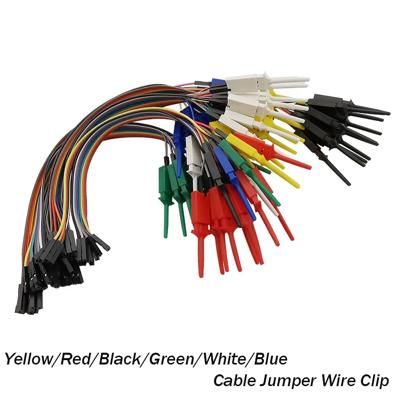
This kit features multi-colored jumper wires terminated with female header connectors on one end and spring-loaded test hook clips on the other. The visual evidence indicates standard 2.54mm pitch female headers, ensuring broad compatibility with breadboards, development boards, and various microcontroller pinouts. These connections are robust. The test hook clips, often referred to as grabber probes, are designed to securely latch onto component leads, IC pins, or header pins without slipping. This provides a stable electrical contact. The spring mechanism within each clip ensures consistent pressure, which is critical for maintaining signal integrity during testing.
The color coding of the wires—yellow, red, black, green, white, and blue—is a fundamental aspect of good electrical practice. This allows for immediate visual identification of different signal lines, power rails, or ground connections. Clear identification prevents miswiring. This systematic approach minimizes setup time and reduces the likelihood of accidental cross-connections, which can be detrimental to sensitive electronic components. The visual distinction is paramount for safety.
Compared to generic jumper wires or alligator clips, these test hook clips offer a superior connection method. Alligator clips can be bulky and prone to shorting adjacent pins, especially on fine-pitch components. Bare jumper wires, while flexible, often require manual holding or can easily detach. This kit provides a secure, isolated connection. The integrated design streamlines the debugging process, allowing engineers to focus on circuit behavior rather than maintaining physical contact.
The visible insulation on the jumper wires appears to be PVC or a similar flexible polymer. This material choice is common for low-voltage applications due to its good dielectric properties and mechanical flexibility. Proper insulation prevents unintended contact. The wire gauge, while not explicitly stated, appears suitable for typical logic-level signals and low-current power distribution found in microcontroller projects. Verifying wire gauge accuracy is crucial for preventing overheating.
Each wire is designed to carry small currents, typically in the milliampere range, making them ideal for signal tracing and logic analysis. Overloading these wires with high currents can lead to insulation breakdown and potential fire hazards. Users must respect current limits. The plastic housing of the test hook clips themselves also contributes to electrical isolation, preventing accidental contact with live terminals. This enhances user safety significantly.
Unlike thin, uninsulated wires that can easily fray or short, these insulated jumper wires maintain their integrity. The robust construction of the clips, with their plastic bodies, provides an additional layer of protection. This design choice ensures longevity. The materials selected are appropriate for repeated use in a laboratory or prototyping environment, offering a cost-effective solution over time.
These test hook clip cables are invaluable for a wide array of diagnostic tasks. They facilitate the connection of logic analyzers to digital circuits, allowing for the capture and analysis of complex signal patterns. Debugging becomes much simpler. They are equally useful for connecting multimeters or oscilloscopes to specific points in a circuit for voltage or waveform measurements, freeing up the user's hands for other tasks. This hands-free operation is a major advantage.
In a scenario where multiple test points need to be monitored simultaneously, such as during the startup sequence of a microcontroller, these color-coded clips simplify the process. Each clip can be assigned to a specific signal, making it easy to track and interpret data. This systematic approach reduces errors. The ability to quickly attach and detach these clips makes iterative testing and modification of circuits much more efficient.
Compared to traditional oscilloscope probes that can be cumbersome for multiple simultaneous connections, this kit offers a more agile solution for low-frequency and logic-level signals. While not designed for high-frequency RF applications, they excel in digital and analog prototyping. They are perfect for breadboard work. The female header end connects directly to standard breadboard pins or development board headers, creating a seamless interface.
As a Certified Electrician, the primary concern with any electrical accessory is safety. While these are low-voltage tools, improper use can still lead to component damage or minor electrical hazards. Users must understand their limitations. The absence of explicit voltage and current ratings on the visible product necessitates caution. It is imperative that these cables are used only within the low-voltage, low-current domains typical of hobbyist electronics and logic analysis, generally below 50V and a few hundred milliamps.
Preventing electrical fires is paramount. Overloading these thin wires with excessive current can cause them to heat up, melt their insulation, and potentially ignite. Always verify wire gauge accuracy against expected current loads. Users should always confirm the power requirements of their circuit before making connections. A simple current calculation can prevent serious issues. Never connect these to mains voltage or high-power circuits. This is a critical safety rule.
Checking terminal quality is another vital aspect. The spring-loaded mechanism of the clips should provide a firm, consistent grip. Loose connections can introduce noise, intermittent signals, or even arcing if current is present. Regularly inspect clips for damage. Any signs of wear, corrosion, or deformation on the metal contacts or plastic housing warrant replacement. Maintaining good terminal quality ensures reliable and safe operation.
The initial investment in a kit like this is quickly recouped through increased efficiency and reduced component damage. Time is money in any project. The ability to quickly set up and tear down test configurations saves valuable time during the development cycle. This accelerates project completion. Furthermore, by providing secure and reliable connections, the risk of accidental shorts that could destroy expensive microcontrollers or integrated circuits is significantly minimized. Protecting components is essential.
This kit represents an upgrade from makeshift wiring solutions. Unlike using bare wires or unreliable clip leads, these purpose-built cables offer a professional and consistent testing environment. The organized, color-coded nature of the kit also contributes to a cleaner workspace. A tidy bench improves focus. This systematic approach to wiring reduces debugging time, allowing engineers and hobbyists to iterate on their designs more rapidly and effectively.
The durability implied by the visible materials suggests a long operational lifespan, even with frequent use. This makes the kit a cost-per-use bargain. The robust plastic clips and insulated wires are designed to withstand the rigors of repeated attachment and detachment. This ensures consistent performance. Investing in quality tools like these ultimately contributes to higher quality project outcomes and a more enjoyable prototyping experience.
Imagine the ease of troubleshooting a complex digital circuit, with each signal line clearly identified and securely connected to your logic analyzer. No more fumbling with tiny probes, no more accidental disconnections, just clear, stable data streams. This kit empowers precise diagnostics, allowing you to pinpoint issues with confidence and speed. It transforms a potentially frustrating debugging session into a streamlined, productive endeavor, bringing your electronic projects to life faster and with greater reliability. This is the capability it provides.
Engineering for Connection Reliability
This kit features multi-colored jumper wires terminated with female header connectors on one end and spring-loaded test hook clips on the other. The visual evidence indicates standard 2.54mm pitch female headers, ensuring broad compatibility with breadboards, development boards, and various microcontroller pinouts. These connections are robust. The test hook clips, often referred to as grabber probes, are designed to securely latch onto component leads, IC pins, or header pins without slipping. This provides a stable electrical contact. The spring mechanism within each clip ensures consistent pressure, which is critical for maintaining signal integrity during testing.
The color coding of the wires—yellow, red, black, green, white, and blue—is a fundamental aspect of good electrical practice. This allows for immediate visual identification of different signal lines, power rails, or ground connections. Clear identification prevents miswiring. This systematic approach minimizes setup time and reduces the likelihood of accidental cross-connections, which can be detrimental to sensitive electronic components. The visual distinction is paramount for safety.
Compared to generic jumper wires or alligator clips, these test hook clips offer a superior connection method. Alligator clips can be bulky and prone to shorting adjacent pins, especially on fine-pitch components. Bare jumper wires, while flexible, often require manual holding or can easily detach. This kit provides a secure, isolated connection. The integrated design streamlines the debugging process, allowing engineers to focus on circuit behavior rather than maintaining physical contact.
Material Science and Insulation Integrity
The visible insulation on the jumper wires appears to be PVC or a similar flexible polymer. This material choice is common for low-voltage applications due to its good dielectric properties and mechanical flexibility. Proper insulation prevents unintended contact. The wire gauge, while not explicitly stated, appears suitable for typical logic-level signals and low-current power distribution found in microcontroller projects. Verifying wire gauge accuracy is crucial for preventing overheating.
Each wire is designed to carry small currents, typically in the milliampere range, making them ideal for signal tracing and logic analysis. Overloading these wires with high currents can lead to insulation breakdown and potential fire hazards. Users must respect current limits. The plastic housing of the test hook clips themselves also contributes to electrical isolation, preventing accidental contact with live terminals. This enhances user safety significantly.
Unlike thin, uninsulated wires that can easily fray or short, these insulated jumper wires maintain their integrity. The robust construction of the clips, with their plastic bodies, provides an additional layer of protection. This design choice ensures longevity. The materials selected are appropriate for repeated use in a laboratory or prototyping environment, offering a cost-effective solution over time.
Operational Versatility in Diagnostics
These test hook clip cables are invaluable for a wide array of diagnostic tasks. They facilitate the connection of logic analyzers to digital circuits, allowing for the capture and analysis of complex signal patterns. Debugging becomes much simpler. They are equally useful for connecting multimeters or oscilloscopes to specific points in a circuit for voltage or waveform measurements, freeing up the user's hands for other tasks. This hands-free operation is a major advantage.
In a scenario where multiple test points need to be monitored simultaneously, such as during the startup sequence of a microcontroller, these color-coded clips simplify the process. Each clip can be assigned to a specific signal, making it easy to track and interpret data. This systematic approach reduces errors. The ability to quickly attach and detach these clips makes iterative testing and modification of circuits much more efficient.
Compared to traditional oscilloscope probes that can be cumbersome for multiple simultaneous connections, this kit offers a more agile solution for low-frequency and logic-level signals. While not designed for high-frequency RF applications, they excel in digital and analog prototyping. They are perfect for breadboard work. The female header end connects directly to standard breadboard pins or development board headers, creating a seamless interface.
Ensuring Electrical Safety and Compliance
As a Certified Electrician, the primary concern with any electrical accessory is safety. While these are low-voltage tools, improper use can still lead to component damage or minor electrical hazards. Users must understand their limitations. The absence of explicit voltage and current ratings on the visible product necessitates caution. It is imperative that these cables are used only within the low-voltage, low-current domains typical of hobbyist electronics and logic analysis, generally below 50V and a few hundred milliamps.
Preventing electrical fires is paramount. Overloading these thin wires with excessive current can cause them to heat up, melt their insulation, and potentially ignite. Always verify wire gauge accuracy against expected current loads. Users should always confirm the power requirements of their circuit before making connections. A simple current calculation can prevent serious issues. Never connect these to mains voltage or high-power circuits. This is a critical safety rule.
Checking terminal quality is another vital aspect. The spring-loaded mechanism of the clips should provide a firm, consistent grip. Loose connections can introduce noise, intermittent signals, or even arcing if current is present. Regularly inspect clips for damage. Any signs of wear, corrosion, or deformation on the metal contacts or plastic housing warrant replacement. Maintaining good terminal quality ensures reliable and safe operation.
Long-Term Value and Prototyping Efficiency
The initial investment in a kit like this is quickly recouped through increased efficiency and reduced component damage. Time is money in any project. The ability to quickly set up and tear down test configurations saves valuable time during the development cycle. This accelerates project completion. Furthermore, by providing secure and reliable connections, the risk of accidental shorts that could destroy expensive microcontrollers or integrated circuits is significantly minimized. Protecting components is essential.
This kit represents an upgrade from makeshift wiring solutions. Unlike using bare wires or unreliable clip leads, these purpose-built cables offer a professional and consistent testing environment. The organized, color-coded nature of the kit also contributes to a cleaner workspace. A tidy bench improves focus. This systematic approach to wiring reduces debugging time, allowing engineers and hobbyists to iterate on their designs more rapidly and effectively.
The durability implied by the visible materials suggests a long operational lifespan, even with frequent use. This makes the kit a cost-per-use bargain. The robust plastic clips and insulated wires are designed to withstand the rigors of repeated attachment and detachment. This ensures consistent performance. Investing in quality tools like these ultimately contributes to higher quality project outcomes and a more enjoyable prototyping experience.
Imagine the ease of troubleshooting a complex digital circuit, with each signal line clearly identified and securely connected to your logic analyzer. No more fumbling with tiny probes, no more accidental disconnections, just clear, stable data streams. This kit empowers precise diagnostics, allowing you to pinpoint issues with confidence and speed. It transforms a potentially frustrating debugging session into a streamlined, productive endeavor, bringing your electronic projects to life faster and with greater reliability. This is the capability it provides.