Precision Micro Linear Actuator for Automation Projects
Official Store Deal
Expert Analysis Overview
Electromechanical Precision for Diverse Applications
The Precision Micro Linear Actuator is a highly adaptable electromechanical component designed for precise motion control in robotics and automation systems. This device offers a compelling solution for projects requiring controlled push-pull functionality across various voltage and stroke configurations. Its compact design and customizable nature make it a strong contender for integration into a wide array of light to medium-duty applications.
Adaptable Power and Stroke Configurations
The product title explicitly details support for 6V, 12V, and 24V DC inputs, alongside multiple stroke lengths including 10mm, 30mm, 50mm, and 100mm. This broad compatibility ensures the actuator can be seamlessly integrated into diverse electrical systems without extensive power conversion requirements. The ability to select specific stroke lengths directly addresses project-specific needs, preventing the common issue of oversized or undersized components.
Such voltage flexibility is crucial for designers working with different power sources, from battery-operated remote controls to industrial 24V automation lines. This versatility minimizes the need for additional voltage regulators, simplifying circuit design and reducing overall system complexity. It's a significant advantage for rapid prototyping and production alike.
Unlike many fixed-voltage actuators, this model's multi-voltage capability allows for greater design freedom. Engineers can standardize on a single actuator type across multiple product lines, even if those lines operate on different power rails. This reduces inventory complexity and streamlines procurement processes.
Operational Speed and Mechanical Integrity
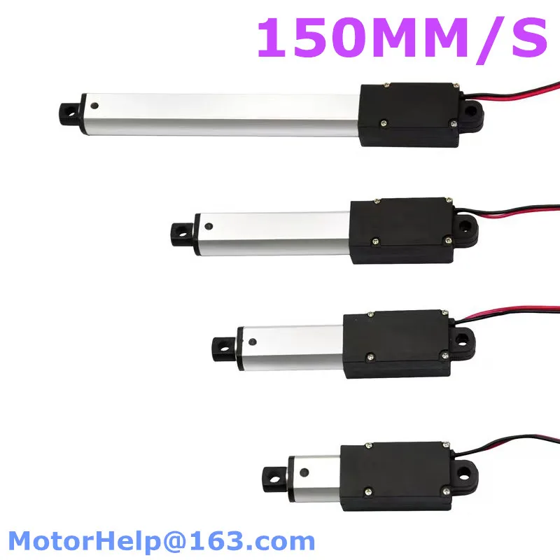
One of the provided images clearly indicates a speed rating of 150MM/S. This speed suggests the actuator is suitable for applications where relatively quick, yet controlled, linear movement is required. The visible construction features a metallic (likely aluminum) extension rod and a black, presumably plastic or composite, motor housing. The rod appears to be of a sufficient gauge for its intended micro-actuator role.
An operating speed of 150mm/s translates to rapid deployment or retraction in many automation scenarios. For instance, in an automated vent system, this speed allows for quick environmental adjustments. The visible robust construction of the extension rod implies good resistance to bending forces during operation. Proper mounting is essential.
Compared to slower, more traditional screw-drive mechanisms, a 150mm/s speed offers a distinct performance advantage for time-sensitive operations. This speed, combined with the compact form factor, positions the actuator as an upgrade for systems currently using manual adjustments or slower electromechanical alternatives. It enhances system responsiveness.
Electrical Safety and Wiring Considerations
The visible wiring consists of two insulated conductors, typically red and black for positive and negative DC connections. The insulation appears to be standard PVC or similar, suitable for low-voltage applications. While specific wire gauge is not explicitly stated, the visible diameter suggests a gauge appropriate for the expected current draw of a micro linear actuator, likely in the range of 18-24 AWG depending on the load and voltage.
Ensuring proper wire gauge is paramount for preventing overheating and potential electrical fires. For 6V, 12V, or 24V systems, the current draw will vary significantly based on the load. Users must calculate the maximum anticipated current and select a power supply and wiring that can safely handle this load, with an appropriate safety margin. Overcurrent protection, such as a fuse or circuit breaker, is always recommended.
Unlike generic, unrated wiring often found in hobbyist components, the visible insulation on these leads appears to meet basic safety expectations for low-voltage DC applications. However, for critical or high-cycle industrial use, verifying specific UL or CE ratings for the wiring and motor assembly would be a prudent step. Always check local electrical codes.
Terminal Quality and Mounting Options
The actuator features mounting points at both ends of the extension rod and the motor housing. These points appear to be designed for clevis-style or pivot mounting, allowing for rotational freedom during linear movement. The terminals for electrical connection are integrated into the motor housing, with leads extending for connection to a control circuit. The quality of these terminals is critical for reliable operation.
Well-designed mounting points facilitate easy integration into various mechanical setups, from simple push-pull mechanisms to more complex robotic linkages. The secure attachment of the electrical leads to the motor housing is vital for long-term reliability, preventing accidental disconnections or shorts. Loose connections can lead to intermittent operation or even arcing.
Many entry-level actuators often feature flimsy mounting tabs or poorly secured wiring. This product's visible mounting points and integrated wiring suggest a more considered design, offering greater stability and ease of installation compared to alternatives requiring custom brackets or delicate wiring procedures. This enhances the overall user experience.
Applications in Robotics and Automation
Given its specifications, this micro linear actuator is well-suited for a range of applications in remote controls, robotics, and automation. Examples include opening/closing small vents, adjusting camera lenses, operating miniature robotic grippers, or providing controlled movement in custom DIY projects. Its precision and compact size are key advantages in these fields.
In robotics, precise linear motion is fundamental for tasks like object manipulation or sensor positioning. The actuator's ability to provide controlled movement makes it an invaluable component for creating articulated joints or extending/retracting Tools. Its small footprint is ideal for compact robot designs.
Compared to bulkier pneumatic cylinders or less precise solenoid actuators, these linear actuators offer fine control and energy efficiency. They provide a direct, electromechanical solution that simplifies design and reduces the need for auxiliary equipment, making them a superior choice for many modern automation challenges. This capability is a significant upgrade.
Long-Term Value and System Integration
The long-term value of this actuator stems from its versatility and apparent robust construction. By offering multiple voltage and stroke options, it reduces the need for specialized components for each project, leading to cost savings over time. Its design appears to prioritize functional longevity within its intended operational parameters.
Investing in a customizable component like this actuator can significantly reduce development time and material costs for projects with varying requirements. Its adaptability means fewer unique parts to source and manage. This translates directly into a better return on investment for both hobbyists and professional integrators.
Unlike cheaper, single-purpose actuators that might require frequent replacement or extensive modification, this product's inherent flexibility and apparent durability offer a more economical long-term solution. It minimizes downtime and maintenance, ensuring projects remain operational and efficient. This is a smart choice for sustained performance.
Imagine a workshop where every automation project, from a smart pet feeder to an automated greenhouse vent, can utilize the same core linear motion component. This actuator simplifies inventory, streamlines design, and ensures consistent, reliable performance across all your creations. It empowers innovation and reduces complexity.
Technical Specifications Overview
Power Input and Control
The actuator is designed to operate on DC power, with options for 6V, 12V, or 24V. This allows for integration into a wide range of low-voltage systems, from battery-powered devices to industrial control panels. The choice of voltage directly impacts the current draw and the type of power supply required. Always match the actuator's voltage to the power source.
Controlling the actuator typically involves reversing the polarity of the DC input to change the direction of the rod's movement. This can be achieved using a DPDT switch, an H-bridge motor driver, or a microcontroller with appropriate driver circuitry. Proper control ensures smooth and precise operation.
Many basic actuators are limited to a single voltage, restricting their application scope. This multi-voltage capability provides a significant advantage, allowing for broader use cases without requiring voltage converters. It simplifies the electrical design for varied projects.
Mechanical Travel and Force
Available stroke lengths are 10mm, 30mm, 50mm, and 100mm. These options cater to different linear travel requirements, from fine adjustments to more substantial movements. The selection of stroke length should be based on the maximum required displacement for the application.
The force output, while not explicitly stated in the title or visible, is inherent to linear actuators. For micro actuators, this typically ranges from a few Newtons to tens of Newtons, suitable for light to medium loads. Overloading the actuator can lead to premature failure of the motor or gearbox.
Compared to manual mechanisms, these actuators offer consistent and repeatable travel. The precise stroke options eliminate guesswork and ensure the mechanism moves exactly as intended. This level of control is critical for automated systems.
Construction Materials and Durability
The visible components include an aluminum extension rod and a black plastic or composite motor housing. Aluminum is chosen for its strength-to-weight ratio and corrosion resistance, making it suitable for the moving rod. The housing protects the internal motor and gearing from environmental factors and mechanical damage.
This combination of materials suggests a balance between durability and weight. The aluminum rod provides the necessary rigidity for linear force transmission, while the housing keeps the sensitive electrical and mechanical components safe. Proper material selection is key to product longevity.
Unlike cheaper actuators that might use all-plastic components, the metallic extension rod offers superior durability and resistance to wear. This material choice indicates a commitment to a more robust product, capable of withstanding repeated cycles. It's a clear upgrade in build quality.
Environmental Considerations
While specific IP ratings are not provided, the enclosed motor housing offers some degree of protection against dust and light splashes. However, for outdoor or harsh industrial environments, additional sealing or protective enclosures would be necessary. Operating temperature ranges are typically standard for small DC motors, usually between -10°C and +50°C.
Understanding the operating environment is crucial for ensuring the actuator's longevity. Exposure to excessive moisture, dust, or extreme temperatures without adequate protection can lead to premature failure. Users should assess their application's environmental conditions carefully.
Many micro actuators are designed for indoor, controlled environments. For applications in more challenging conditions, this actuator, like most in its class, would benefit from supplementary environmental protection. This is a common consideration for electromechanical components.
Operational Guidelines and Best Practices
Power Supply Matching
Always ensure the power supply voltage matches the actuator's rated voltage (6V, 12V, or 24V). Using an incorrect voltage can damage the motor or significantly reduce its lifespan. Verify the power supply can provide sufficient current for the actuator under maximum load conditions.
An undersized power supply will cause the actuator to perform sluggishly or stall under load. An oversized voltage will lead to overheating and rapid component degradation. Proper power matching is fundamental for optimal performance and safety. Always check the specifications.
Unlike simple resistive loads, motors have inrush current requirements. Ensure your power supply can handle these momentary spikes without voltage sag. This prevents erratic behavior and protects both the actuator and the power source.
Mounting and Alignment
Mount the actuator securely using the provided or recommended brackets. Ensure proper alignment of the actuator with the load it is moving to prevent side loading on the extension rod. Side loading can cause excessive wear on internal components and lead to premature failure. A straight pull or push is ideal.
Incorrect mounting can introduce binding or friction, increasing the current draw and reducing efficiency. Take time to ensure the actuator's path of motion is perfectly aligned with the object it is intended to move. This attention to detail extends the actuator's life.
Many issues with linear actuators stem from poor mechanical integration rather than electrical faults. Unlike simple solenoids, linear actuators require careful alignment to perform optimally. This is a critical step often overlooked by new users.
Overload Protection
Implement overcurrent protection (e.g., a fuse or current-limiting circuit) in the power supply line. This protects the actuator and the power supply from damage in case of a mechanical jam or excessive load. Select a fuse rating slightly above the actuator's maximum operating current.
Overloading the actuator can cause the motor to draw excessive current, leading to overheating and potential burnout. A fuse acts as a sacrificial component, protecting the more expensive actuator from irreversible damage. It's a small investment for significant protection.
Unlike simple on/off switches, proper overload protection actively monitors current and disconnects power when unsafe levels are detected. This proactive safety measure is superior to relying solely on the motor's internal thermal protection, which may react too slowly.
Duty Cycle Considerations
Linear actuators typically have a specified duty cycle, indicating the percentage of time they can operate continuously within a given period. For micro actuators, this is often not 100%. Allow the actuator to cool down between cycles to prevent overheating, especially under heavy loads. Consult the manufacturer's data sheet for specific duty cycle recommendations.
Exceeding the recommended duty cycle can lead to thermal stress on the motor windings and gearbox components, shortening the actuator's lifespan. Plan your automation sequences to incorporate rest periods. This ensures the actuator operates within its safe thermal limits.
Many users assume continuous operation is possible, but most electromechanical devices have thermal limitations. Understanding and adhering to the duty cycle is a key differentiator between a short-lived component and one that provides years of reliable service. This is a professional approach to system design.
This customizable micro linear actuator presents a robust and flexible solution for a multitude of automation and robotics challenges. Its multi-voltage support, varied stroke lengths, and respectable speed make it a valuable asset for engineers and hobbyists alike. By adhering to proper electrical and mechanical integration practices, users can expect reliable and precise linear motion for their projects. Imagine the possibilities of seamlessly integrating controlled movement into your next innovative design, knowing you have a dependable component at its core.