PL259 UHF Male Solder Connector for RG58/RG142/LMR195/RG400 Coaxial Cable
Official Store Deal
Expert Analysis Overview
Precision RF Connectivity: An Electrician's Perspective
The PL259 UHF Male Solder Connector is a critical component designed for reliable radio frequency signal transmission in demanding coaxial cable applications. This connector type, specifically the PL259, is widely recognized for its robust design and suitability for frequencies up to 300 MHz, making it a staple in amateur radio, CB radio, and various industrial RF systems. The brass and copper construction, as highlighted in the product description, indicates a commitment to both electrical performance and mechanical durability, essential for maintaining signal integrity over time. This is not merely a piece of hardware; it is a foundational element for stable communication.Material Composition and Durability Assessment
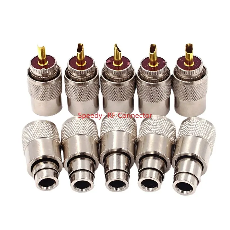
The connectors visibly feature brass and copper construction, as indicated by the product description and the metallic sheen in the images. The outer shell exhibits a knurled texture, suggesting enhanced grip during installation. This material choice directly impacts the connector's longevity and electrical conductivity. Brass provides structural integrity and corrosion resistance, while copper ensures optimal signal path performance. The knurling aids in secure hand-tightening, preventing loose connections that could degrade signal quality.Unlike lower-grade connectors often utilizing nickel-plated steel, the brass and copper core of these PL259 units offers superior conductivity and reduced signal loss, particularly at higher frequencies. This translates to a more stable and efficient RF system compared to standard entry-level alternatives. The use of high-quality metals minimizes resistive losses, a critical factor in RF systems where every decibel of signal strength matters.
From an electrical standpoint, the choice of brass and copper is paramount. These materials possess excellent electrical conductivity, which is crucial for minimizing signal attenuation and ensuring efficient power transfer. The robust construction also contributes to the connector's mechanical stability, resisting deformation or damage during repeated connection and disconnection cycles. This material integrity is a key differentiator, ensuring the connector performs reliably under various environmental stresses.
Coaxial Cable Compatibility and Termination Integrity
This PL259 connector is specified for use with RG58, RG142, LMR195, and RG400 coaxial cables. This broad compatibility covers a range of common RF cable types, from flexible general-purpose RG58 to more robust, low-loss options like RG142 and RG400. The design necessitates a solder termination for the center conductor, a method favored by many professionals for its superior electrical connection and mechanical strength compared to crimp-only alternatives.Proper termination is vital for RF performance. A well-executed solder joint ensures minimal impedance discontinuity at the connection point, preventing signal reflections and standing wave ratio (SWR) issues. The solder method, while requiring more skill and specialized tools, provides a permanent, low-resistance connection that is less prone to intermittent faults or signal degradation over time. This contrasts sharply with poorly executed crimp connections that can introduce significant signal loss and noise.
When working with these specified cables, electricians must ensure precise stripping of the cable jacket, braid, and dielectric. The inner conductor must be clean and properly tinned before soldering to the connector's center pin. This meticulous preparation is non-negotiable for achieving the advertised performance and preventing common RF issues. The connector's design appears to accommodate the typical dimensions of these cable types, facilitating a proper fit and termination.
Electrical Performance and Signal Transmission
UHF connectors, including the PL259, are designed for general-purpose RF applications, typically performing well up to 300 MHz, though they can be used at higher frequencies with some performance degradation. The solid brass and copper construction directly supports this performance envelope by providing a low-resistance path for the RF signal. The impedance of the PL259 connector itself is nominally non-constant, often cited as around 50 ohms when properly terminated, but it is not a true 50-ohm connector across its entire frequency range.For applications requiring precise impedance matching, such as high-frequency data transmission or sensitive instrumentation, alternative connector types like N-type or SMA might be preferred. However, for the intended applications of amateur radio and CB, the PL259's performance is generally more than adequate. The key is ensuring the cable itself is matched to the system's impedance, typically 50 ohms, and that the termination is executed flawlessly to minimize reflections.
The robust nature of the solder connection, when performed correctly, ensures that the electrical path remains stable even under vibration or mechanical stress. This stability is crucial for maintaining consistent signal strength and preventing intermittent communication failures. Unlike connectors with less secure contact mechanisms, a soldered PL259 offers a dependable electrical interface, which is a significant advantage in field installations or mobile setups.
Installation Considerations and Best Practices
Installing these solder-type PL259 connectors requires specific tools and a methodical approach. Essential equipment includes a soldering iron with adequate wattage, solder, flux, a cable stripper, and potentially a vise or third-hand tool to hold the connector and cable steady. Proper ventilation is also critical when soldering to avoid inhaling fumes. This is a hands-on process.Begin by carefully stripping the coaxial cable to the correct dimensions for the PL259. The center conductor, dielectric, and braid must be exposed precisely. The outer shell and braid clamp are then slid onto the cable. The center conductor is soldered to the connector's pin, ensuring a strong mechanical and electrical bond without excessive heat that could damage the dielectric. The braid is then fanned out and soldered to the connector body through the access holes, or crimped if a crimp sleeve is used (though this product implies solder for the main body as well).
Finally, the outer shell is threaded onto the connector body, securing the entire assembly. It is imperative to check for continuity and shorts using a multimeter after termination. An RF analyzer or SWR meter should then be used to verify the electrical performance of the terminated cable assembly. This systematic approach minimizes errors and ensures the connector performs as expected, preventing costly rework or system failures.