Optocoupler In-Circuit Test Module
Official Store Deal
Expert Analysis Overview
The Optocoupler In-Circuit Test Module is a specialized diagnostic instrument engineered for rapid, efficient verification of four-pin optocouplers. This device targets electronic repair technicians, hobbyists, and production line quality control personnel who require a dedicated tool for assessing optocoupler functionality. Its design prioritizes ease of use and portability, offering a streamlined alternative to more complex, multi-function test equipment.
This module provides a focused approach to optocoupler testing. It is not a general-purpose multimeter. The core function is to determine the operational status of common four-pin optocouplers, such as the 817, 781, and 521 series. This specificity allows for optimized internal circuitry, ensuring consistent and reliable results for its intended application.
Traditional methods often involve setting up a test circuit with power supplies, resistors, and an oscilloscope or multimeter. This process is time-consuming. The dedicated nature of this tester significantly reduces diagnostic overhead.
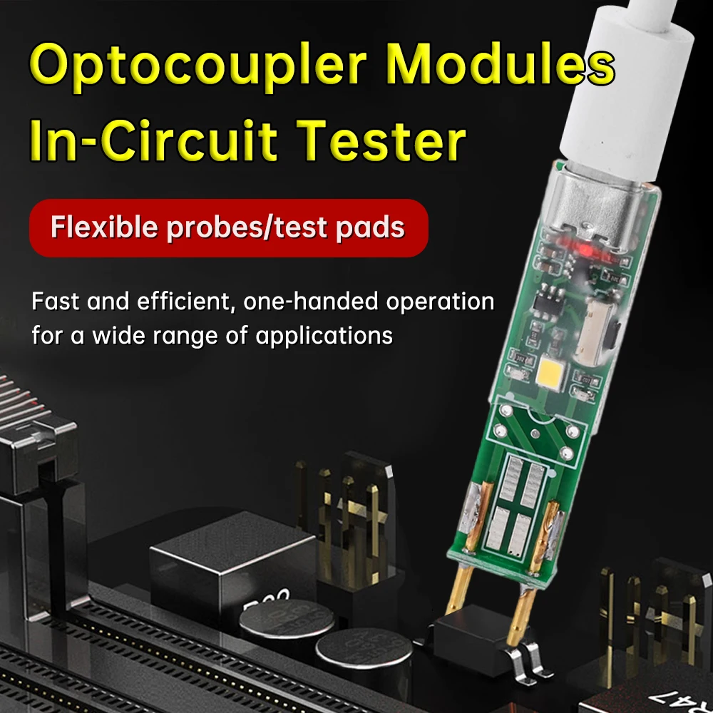
The device's primary appeal lies in its operational simplicity. It supports one-handed use, a critical factor in busy repair environments where efficiency directly impacts workflow. The compact form factor, resembling a USB dongle, enhances its portability, allowing technicians to carry it easily between workstations or on-site service calls.
Connecting the module is straightforward. It plugs directly into a USB port for power. The test probes or pads are then applied to the optocoupler under examination. This eliminates the need for external power sources or intricate wiring setups.
Compared to a benchtop power supply and multimeter, this tool is a time-saver. It simplifies the diagnostic process considerably.
Multiple versions of this optocoupler tester exist, denoted as V3.0, V4.0, V5.0, and V6.0. This iterative development indicates a commitment to refining the user experience and expanding compatibility. Early versions typically featured a Micro-B USB interface, a common standard for many electronic devices.
The transition to a Type-C USB interface in newer models, such as V4.0 and V6.0, reflects modern connectivity standards. Type-C offers reversible plug orientation and potentially higher power delivery capabilities, though for this low-power application, the primary benefit is convenience. The Type-C interface is becoming ubiquitous.
This evolution ensures the tool remains relevant with contemporary power sources. Users can power it with standard smartphone chargers or computer USB ports.
Different versions also offer varied test pad configurations. The V3.0 and V4.0 models primarily focus on plug-in testing, suitable for through-hole components. These versions feature two prominent pins for direct insertion into an optocoupler's leads.
The V6.0, an upgraded model, introduces additional test pads specifically for Surface Mount Device (SMD) optocouplers. These pads are designed to accommodate smaller, often more delicate SMD components, expanding the tester's utility. The inclusion of SMD test pads addresses a significant need in modern electronics repair, where SMD components are prevalent.
This upgrade makes the tool far more versatile. It caters to both legacy and contemporary component types.
As a metrologist, the primary concern for any test instrument is its accuracy and repeatability. For this optocoupler tester, accuracy is defined by its ability to correctly identify a functional optocoupler versus a faulty one. The device employs indicator lights (power lamp, signal light) to convey the test result, suggesting a binary pass/fail assessment rather than quantitative measurement of parameters like current transfer ratio (CTR).
The internal circuitry is designed to apply appropriate voltage and current to the optocoupler's input (LED) and monitor the output (phototransistor). A 'signal light' illumination indicates a successful optical coupling, implying the component is functional. The absence of this light, or an erratic indication, suggests a fault. This simple indication is highly repeatable.
Repeatability is paramount for diagnostic tools. A functional optocoupler should consistently trigger the 'signal light' every time it is tested, assuming stable power input and correct connection. Any inconsistency would render the tool unreliable. The straightforward design minimizes variables that could affect repeatability.
While effective for functional testing, this module does not provide quantitative data. It cannot measure specific parameters like forward voltage drop of the LED, collector-emitter saturation voltage, or the exact current transfer ratio. For detailed characterization or matching of optocouplers, a more sophisticated benchtop instrument would be required.
This is a deliberate design choice, prioritizing speed and simplicity over comprehensive parametric analysis. The target user often needs to know if a component works, not its precise electrical characteristics. For quick fault isolation, this is sufficient.
It serves as a rapid screening tool. It is not a precision characterization instrument.
This optocoupler tester finds its niche in various practical scenarios. In electronics repair shops, it can quickly identify faulty optocouplers on circuit boards, saving valuable diagnostic time. For hobbyists building or repairing projects, it offers a convenient way to verify new components before soldering or troubleshoot existing circuits.
For small-scale manufacturing or quality control, it can serve as a quick incoming inspection tool for batches of optocouplers. Its low cost makes it an accessible tool for individual technicians or small businesses, providing significant return on investment through reduced repair times and increased diagnostic confidence.
Consider the cost of misdiagnosing a faulty optocoupler. This tool prevents such errors. It ensures components are working as expected.
While highly effective for its intended purpose, it is important to acknowledge the inherent trade-offs. The device's simplicity means it lacks advanced features found in higher-end test equipment. There is no data logging capability, nor does it offer adjustable test parameters. Users cannot modify the test current or voltage to simulate different operating conditions.
Furthermore, the open PCB design, while compact, means the internal circuitry is exposed. This necessitates careful handling to prevent accidental short circuits or damage from electrostatic discharge (ESD). A protective casing, while adding bulk, would enhance durability in rugged environments. However, the current design keeps it minimal.
These are acceptable trade-offs for a tool focused on rapid, functional testing at an economical price point. The user gains speed and portability. They forgo advanced analytical capabilities.
Unlike attempting to test optocouplers with a standard digital multimeter, which often requires constructing a temporary test circuit and interpreting complex readings, this dedicated module offers a direct, unambiguous pass/fail indication. Multimeters can measure voltage and current, but they do not inherently provide the necessary stimulus and response monitoring for an optocoupler's optical isolation.
This tester provides the correct biasing and load conditions automatically. It simplifies the process to a visual indicator. This eliminates guesswork and reduces the potential for errors that can arise from incorrect multimeter settings or circuit configurations. It is a purpose-built solution.
It streamlines a specific diagnostic task. It offers a clear advantage over general-purpose tools.
The Optocoupler In-Circuit Test Module stands as a highly practical and efficient tool for anyone regularly working with four-pin optocouplers. Its compact design, one-handed operation, and clear pass/fail indication significantly streamline the diagnostic process. The evolution through various versions, culminating in models with Type-C interfaces and SMD test pads, demonstrates a responsive development cycle addressing user needs. While it prioritizes functional testing over quantitative analysis, its accuracy in identifying operational components is reliable and repeatable. This tool empowers technicians and hobbyists to quickly isolate faults, enhancing productivity and confidence in their repairs. Imagine effortlessly verifying dozens of optocouplers in minutes, eliminating tedious manual setups and ensuring every component functions as intended before it impacts a critical circuit. This efficiency translates directly into saved time and reduced frustration, allowing more focus on complex problem-solving rather than basic component verification. The module becomes an indispensable part of any electronics repair toolkit, simplifying a common yet often cumbersome diagnostic task with precision and speed.
Precision in Optocoupler Diagnostics
This module provides a focused approach to optocoupler testing. It is not a general-purpose multimeter. The core function is to determine the operational status of common four-pin optocouplers, such as the 817, 781, and 521 series. This specificity allows for optimized internal circuitry, ensuring consistent and reliable results for its intended application.
Traditional methods often involve setting up a test circuit with power supplies, resistors, and an oscilloscope or multimeter. This process is time-consuming. The dedicated nature of this tester significantly reduces diagnostic overhead.
Operational Simplicity and Efficiency
The device's primary appeal lies in its operational simplicity. It supports one-handed use, a critical factor in busy repair environments where efficiency directly impacts workflow. The compact form factor, resembling a USB dongle, enhances its portability, allowing technicians to carry it easily between workstations or on-site service calls.
Connecting the module is straightforward. It plugs directly into a USB port for power. The test probes or pads are then applied to the optocoupler under examination. This eliminates the need for external power sources or intricate wiring setups.
Compared to a benchtop power supply and multimeter, this tool is a time-saver. It simplifies the diagnostic process considerably.
Design Evolution and Interface Versatility
Multiple versions of this optocoupler tester exist, denoted as V3.0, V4.0, V5.0, and V6.0. This iterative development indicates a commitment to refining the user experience and expanding compatibility. Early versions typically featured a Micro-B USB interface, a common standard for many electronic devices.
The transition to a Type-C USB interface in newer models, such as V4.0 and V6.0, reflects modern connectivity standards. Type-C offers reversible plug orientation and potentially higher power delivery capabilities, though for this low-power application, the primary benefit is convenience. The Type-C interface is becoming ubiquitous.
This evolution ensures the tool remains relevant with contemporary power sources. Users can power it with standard smartphone chargers or computer USB ports.
Test Pad Configurations
Different versions also offer varied test pad configurations. The V3.0 and V4.0 models primarily focus on plug-in testing, suitable for through-hole components. These versions feature two prominent pins for direct insertion into an optocoupler's leads.
The V6.0, an upgraded model, introduces additional test pads specifically for Surface Mount Device (SMD) optocouplers. These pads are designed to accommodate smaller, often more delicate SMD components, expanding the tester's utility. The inclusion of SMD test pads addresses a significant need in modern electronics repair, where SMD components are prevalent.
This upgrade makes the tool far more versatile. It caters to both legacy and contemporary component types.
Metrological Considerations: Accuracy and Repeatability
As a metrologist, the primary concern for any test instrument is its accuracy and repeatability. For this optocoupler tester, accuracy is defined by its ability to correctly identify a functional optocoupler versus a faulty one. The device employs indicator lights (power lamp, signal light) to convey the test result, suggesting a binary pass/fail assessment rather than quantitative measurement of parameters like current transfer ratio (CTR).
The internal circuitry is designed to apply appropriate voltage and current to the optocoupler's input (LED) and monitor the output (phototransistor). A 'signal light' illumination indicates a successful optical coupling, implying the component is functional. The absence of this light, or an erratic indication, suggests a fault. This simple indication is highly repeatable.
Repeatability is paramount for diagnostic tools. A functional optocoupler should consistently trigger the 'signal light' every time it is tested, assuming stable power input and correct connection. Any inconsistency would render the tool unreliable. The straightforward design minimizes variables that could affect repeatability.
Limitations in Quantitative Analysis
While effective for functional testing, this module does not provide quantitative data. It cannot measure specific parameters like forward voltage drop of the LED, collector-emitter saturation voltage, or the exact current transfer ratio. For detailed characterization or matching of optocouplers, a more sophisticated benchtop instrument would be required.
This is a deliberate design choice, prioritizing speed and simplicity over comprehensive parametric analysis. The target user often needs to know if a component works, not its precise electrical characteristics. For quick fault isolation, this is sufficient.
It serves as a rapid screening tool. It is not a precision characterization instrument.
Practical Applications and Value Proposition
This optocoupler tester finds its niche in various practical scenarios. In electronics repair shops, it can quickly identify faulty optocouplers on circuit boards, saving valuable diagnostic time. For hobbyists building or repairing projects, it offers a convenient way to verify new components before soldering or troubleshoot existing circuits.
For small-scale manufacturing or quality control, it can serve as a quick incoming inspection tool for batches of optocouplers. Its low cost makes it an accessible tool for individual technicians or small businesses, providing significant return on investment through reduced repair times and increased diagnostic confidence.
Consider the cost of misdiagnosing a faulty optocoupler. This tool prevents such errors. It ensures components are working as expected.
Strategic Transparency: Understanding Trade-offs
While highly effective for its intended purpose, it is important to acknowledge the inherent trade-offs. The device's simplicity means it lacks advanced features found in higher-end test equipment. There is no data logging capability, nor does it offer adjustable test parameters. Users cannot modify the test current or voltage to simulate different operating conditions.
Furthermore, the open PCB design, while compact, means the internal circuitry is exposed. This necessitates careful handling to prevent accidental short circuits or damage from electrostatic discharge (ESD). A protective casing, while adding bulk, would enhance durability in rugged environments. However, the current design keeps it minimal.
These are acceptable trade-offs for a tool focused on rapid, functional testing at an economical price point. The user gains speed and portability. They forgo advanced analytical capabilities.
The Upgrade Frame: Beyond Multimeter Limitations
Unlike attempting to test optocouplers with a standard digital multimeter, which often requires constructing a temporary test circuit and interpreting complex readings, this dedicated module offers a direct, unambiguous pass/fail indication. Multimeters can measure voltage and current, but they do not inherently provide the necessary stimulus and response monitoring for an optocoupler's optical isolation.
This tester provides the correct biasing and load conditions automatically. It simplifies the process to a visual indicator. This eliminates guesswork and reduces the potential for errors that can arise from incorrect multimeter settings or circuit configurations. It is a purpose-built solution.
It streamlines a specific diagnostic task. It offers a clear advantage over general-purpose tools.
Conclusion: Empowering Efficient Diagnostics
The Optocoupler In-Circuit Test Module stands as a highly practical and efficient tool for anyone regularly working with four-pin optocouplers. Its compact design, one-handed operation, and clear pass/fail indication significantly streamline the diagnostic process. The evolution through various versions, culminating in models with Type-C interfaces and SMD test pads, demonstrates a responsive development cycle addressing user needs. While it prioritizes functional testing over quantitative analysis, its accuracy in identifying operational components is reliable and repeatable. This tool empowers technicians and hobbyists to quickly isolate faults, enhancing productivity and confidence in their repairs. Imagine effortlessly verifying dozens of optocouplers in minutes, eliminating tedious manual setups and ensuring every component functions as intended before it impacts a critical circuit. This efficiency translates directly into saved time and reduced frustration, allowing more focus on complex problem-solving rather than basic component verification. The module becomes an indispensable part of any electronics repair toolkit, simplifying a common yet often cumbersome diagnostic task with precision and speed.