Multi-Color 7-Segment LED Displays (3 & 4-Digit)
Official Store Deal
Expert Analysis Overview
Precision Visual Feedback for Electronic Systems
These 7-segment LED displays are fundamental components for presenting numerical and limited alphanumeric data in electronic projects. They are a versatile choice for engineers and hobbyists requiring direct, segment-based visual output. The product offers a selection of common anode or common cathode configurations, crucial for seamless integration with various microcontrollers and driver circuits. This flexibility is paramount for custom circuit design.
Engineering Visual Feedback
Seven-segment displays are optoelectronic devices that illuminate specific segments to form digits. Each display consists of seven individual LEDs, typically arranged in a figure-eight pattern, plus an optional decimal point. This allows for clear numerical representation. The simplicity of their operation makes them ideal for a wide array of applications, from basic digital clocks to complex industrial control panels. They provide immediate, unambiguous data.
Integrating these displays into a circuit requires careful consideration of current limiting resistors. Without proper resistance, the LEDs will draw excessive current, leading to rapid degradation or catastrophic failure. This is a critical safety and longevity concern. Unlike more complex graphical displays, 7-segment units offer a direct, low-overhead method for numerical output, reducing processing demands on the host microcontroller. Their straightforward design ensures reliable operation in many environments.
Configuration Versatility: Common Anode vs. Common Cathode
The distinction between common anode and common cathode configurations is fundamental to proper circuit design. A common anode display connects all LED anodes to a single positive voltage supply, requiring individual segments to be activated by grounding their respective cathodes. Conversely, a common cathode display connects all LED cathodes to a common ground, with segments activated by applying a positive voltage to their anodes. This choice dictates the type of driver circuitry required.
Selecting the correct configuration ensures compatibility with the chosen microcontroller or driver IC. For instance, a microcontroller with active-low output drivers pairs efficiently with common anode displays. Conversely, active-high output drivers are suitable for common cathode displays. Incorrect pairing can lead to complex and inefficient interfacing, or even component damage. Understanding these configurations prevents wiring errors.
This inherent flexibility, offering both common anode and common cathode options, provides significant design freedom. Unlike fixed-configuration display modules, these individual components allow the designer to select the optimal type for their specific system architecture. This adaptability reduces the need for additional level-shifting circuitry, simplifying the overall design and improving system reliability. It is a core design decision.
Chromatic Options and Visibility
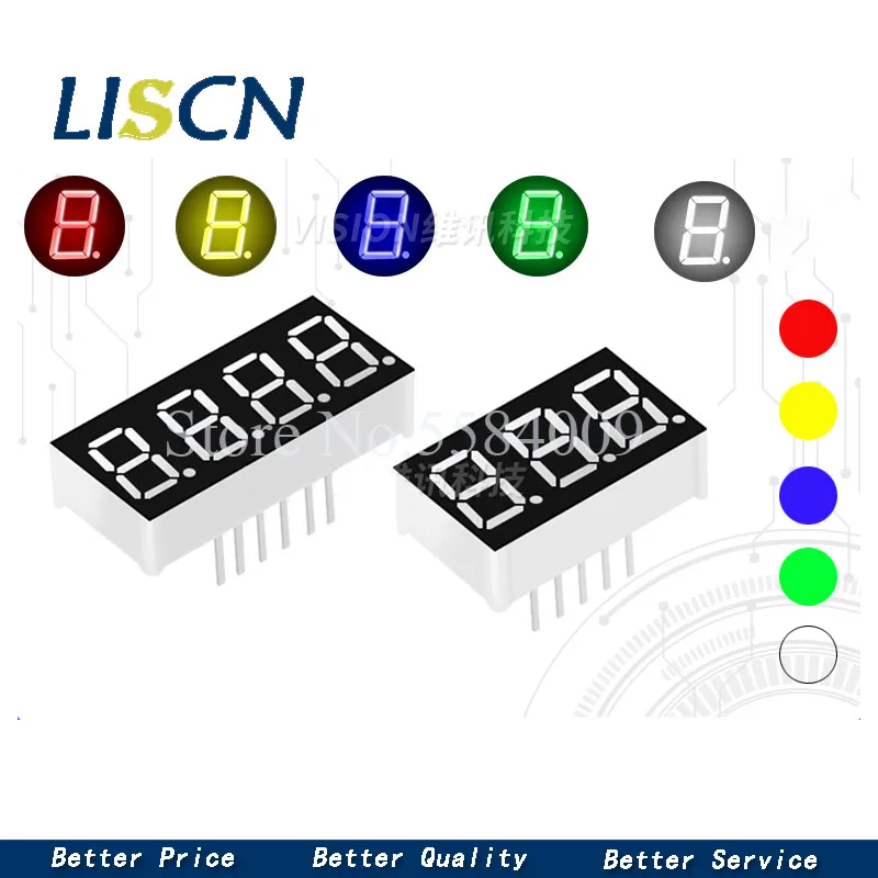
The availability of multiple LED colors—Green, Blue, White, and Red—allows for tailored visual aesthetics and functional differentiation. Red displays are traditionally used for warnings or basic numerical readouts due to their high visibility and historical prevalence. Green often signifies 'safe' or 'active' states, while blue and white offer a more modern, crisp appearance, often preferred in contemporary designs. Each color has distinct wavelength characteristics.
Color choice significantly impacts readability under various ambient lighting conditions. High-contrast colors, like red or green, perform well in bright environments. Blue and white, while aesthetically pleasing, may require careful consideration of display filters or enclosures to maintain optimal visibility in direct sunlight. The perceived brightness also varies between colors, even at the same current. This affects user experience.
Compared to monochrome displays that offer only a single color, this selection provides designers with a palette to enhance user interfaces. Different colors can be used to indicate different parameters or states within a single system, improving intuitive understanding. For example, a red display for temperature and a green display for humidity. This enhances system communication.
Dimensional Adaptability: Size Variants
The product offers three distinct display sizes: 0.28, 0.36, and 0.56 inches. These dimensions refer to the height of the individual digits. The 0.28-inch displays are compact, ideal for space-constrained applications such as small handheld devices or embedded systems where panel real estate is limited. They are very small.
Medium-sized 0.36-inch displays strike a balance between compactness and readability, suitable for desktop instruments, test equipment, or consumer electronics. They offer good visibility without consuming excessive space. The largest 0.56-inch displays are designed for applications requiring high visibility from a distance, such as public information displays, large clock faces, or industrial machinery where operators need to read data quickly from several feet away. Visibility is key here.
The choice of display size involves trade-offs between physical footprint, power consumption, and viewing distance. Larger displays generally require more current per segment to achieve comparable brightness, impacting overall power budget. However, their enhanced readability can be a critical functional requirement. Designers must balance these factors.
Digit Count and Data Presentation
These displays are available in 3-digit and 4-digit configurations. A 3-digit display is suitable for presenting values up to 999, commonly used for simple counters, timers, or basic sensor readings. It is a straightforward option. A 4-digit display extends this capability to 9999, making it ideal for applications requiring a wider range of numerical representation, such as precise temperature readouts, frequency counters, or time displays with seconds. More digits mean more data.
Managing multiple digits typically involves multiplexing. This technique rapidly switches the power to each digit sequentially, creating the illusion that all digits are lit simultaneously. This reduces the number of I/O pins required from a microcontroller and lowers the instantaneous current draw. Proper multiplexing timing is crucial to avoid flicker. It saves pins.
Unlike single-digit displays that require multiple discrete units for multi-digit readouts, these integrated 3-digit and 4-digit modules simplify assembly and wiring. This integration streamlines the design process and reduces potential points of failure. The choice between 3 and 4 digits depends directly on the numerical range and precision required by the application.
Electrical Integrity and Longevity
Ensuring the electrical integrity of these LED displays is paramount for both performance and safety. Each LED segment requires a current-limiting resistor in series to prevent overcurrent. Without these resistors, the low forward voltage of the LEDs would cause them to draw excessive current, leading to immediate burnout or significantly reduced lifespan. Resistors are non-negotiable.
Improper current management poses a significant risk. Overcurrent can cause the LED junction temperature to rise rapidly, leading to thermal runaway and eventual failure. In extreme cases, sustained overcurrent can generate enough heat to melt solder joints or damage adjacent components, potentially leading to electrical fires. This is a serious safety concern. Adhering to manufacturer specifications for forward current is essential.
Best practices for integrating these displays include calculating the appropriate resistor value based on the LED's forward voltage, the desired forward current, and the supply voltage. Using a stable power supply and incorporating proper decoupling capacitors can further enhance reliability. Verifying wire gauge accuracy for connections, especially in higher current applications, is also a critical step for preventing voltage drop and overheating. Always check terminal quality.
System Integration and Control
These 7-segment displays are designed for direct interfacing with microcontrollers such as Arduino, ESP32, or PIC microcontrollers. The control logic involves setting the state of each segment pin (and digit common pin for multiplexed displays) to illuminate the desired pattern. This direct control offers maximum flexibility for custom character generation or display sequences. It is highly customizable.
While direct control is possible, using dedicated 7-segment display driver ICs, such as the CD4511 (for common cathode) or the 74LS47 (for common anode), can simplify the interface. These ICs typically accept BCD (Binary Coded Decimal) input and automatically convert it to the appropriate 7-segment pattern, reducing the number of microcontroller pins required. This simplifies coding.
Unlike pre-built display modules that often come with integrated drivers and fixed communication protocols (e.g., I2C, SPI), these individual displays provide the raw capability for custom driver implementation. This allows engineers to optimize for specific power requirements, refresh rates, or form factors. The