Micro USB 2.0 Male DIY Connectors
Official Store Deal
Expert Analysis Overview
Precision Connectivity for DIY Electronics
The Micro USB 2.0 Male connector is a fundamental component for low-power data and charging applications, primarily serving DIY electronics enthusiasts and repair technicians. This offering of bulk connectors provides a cost-effective solution for projects requiring reliable Micro USB integration, emphasizing the importance of proper electrical assembly for safe and functional outcomes.Structural Integrity and Material Composition
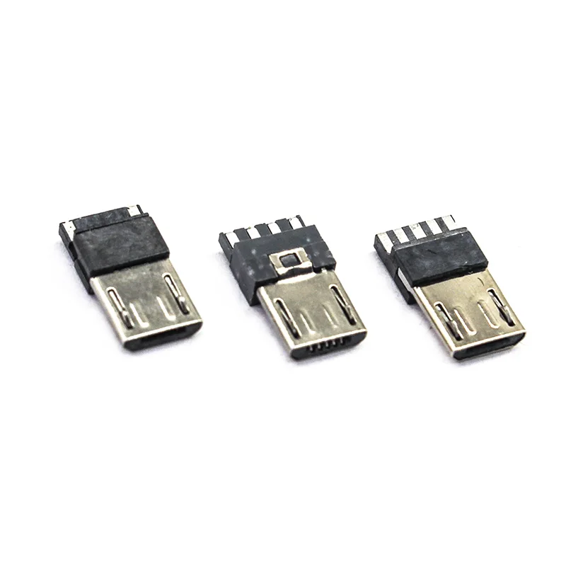
The visible construction of these Micro USB 2.0 male connectors features a metallic outer shell, typically nickel-plated steel, which provides mechanical protection and acts as a ground shield. This shell is crucial for durability, especially in applications where the connector will experience frequent insertions and removals. The internal insulation block, made from a black polymer, securely houses the conductive pins.This metallic casing is designed to withstand the physical stresses of connection cycles. A robust shell prevents deformation, which could lead to intermittent connections or complete failure. The material choice directly impacts the connector's lifespan.
Compared to connectors with thinner or less robust metal housings, these appear to offer a standard level of physical resilience. The visible crimping points on the metal shell suggest a secure attachment to the internal plastic, a common and effective manufacturing technique.
Pin Configuration and Electrical Pathways
These connectors are available in both 4-pin and 5-pin configurations, catering to different Micro USB 2.0 requirements. The 5-pin variant includes an ID pin, which is essential for USB On-The-Go (OTG) functionality, allowing a device to act as a host. The 4-pin version typically omits this ID pin, suitable for standard charging and data transfer where host capabilities are not needed.Each pin serves a specific electrical function: VBUS (power), D
Standard Micro USB 2.0 specifications dictate the voltage and current ratings for these pins. The VBUS pin typically carries 5V DC, with current capabilities up to 500mA for standard USB 2.0, though some charging protocols can push this higher. Ensuring the connected circuit adheres to these limits is critical for safety and performance, preventing overheating or component stress.
Data Transfer and Power Delivery Capabilities
Adhering to the USB 2.0 standard, these connectors support data transfer rates up to 480 Mbps (Megabits per second). This speed is sufficient for most peripheral connections, including charging, file transfers to and from smartphones, and connecting various low-bandwidth devices. The data lines (D+ and D-) are differential pairs, requiring careful routing and shielding in custom PCB designs to maintain signal integrity.For power delivery, the VBUS and GND pins are responsible for supplying 5V DC. The current capacity is inherently limited by the USB 2.0 specification and the physical properties of the connector pins themselves. Overloading these pins can lead to excessive heat generation, potentially melting the plastic insulator or causing a fire hazard. Proper wire gauge selection is essential.
Unlike USB 3.0 or USB-C connectors, Micro USB 2.0 does not support higher power delivery profiles or significantly faster data rates. This makes these connectors ideal for legacy devices or projects where advanced capabilities are not required, offering a simpler and often more compact solution.
Application in DIY and Repair Scenarios
These bulk connectors are specifically marketed for DIY projects and repairs, offering flexibility for custom cable assemblies, device prototyping, or replacing damaged ports on existing electronics. Their availability in packs of 20, 50, or 100 units makes them suitable for hobbyists, small-scale manufacturers, or repair shops that frequently work with Micro USB interfaces.Integrating these connectors into a circuit requires precise soldering techniques. The small pitch of the pins demands a steady hand, appropriate soldering iron tip size, and good quality solder. Cold solder joints or solder bridges between pins are common failure points that can lead to intermittent connections or short circuits.
Compared to purchasing pre-made cables, these individual connectors offer significant cost savings for bulk applications. They also provide the freedom to create custom cable lengths or specialized wiring harnesses, which is invaluable for unique project requirements where off-the-shelf solutions are inadequate.
Electrical Safety and Compliance Considerations
As generic components, these connectors typically do not carry specific UL, CE, or other regulatory certifications on their own. The responsibility for ensuring the safety and compliance of the final assembled product rests entirely with the user or manufacturer. This includes proper insulation, strain relief, and adherence to voltage and current limits.Preventing electrical fires is paramount. This involves meticulous attention to soldering quality, ensuring no stray strands of wire or solder bridges create unintended conductive paths. Adequate insulation around the solder joints is also critical to prevent accidental contact with other components or the device casing.
Unlike branded, pre-certified cables, these raw components require the user to implement all necessary safety measures. This includes verifying the wire gauge used for power and data lines, ensuring it can safely carry the intended current without overheating. A thorough understanding of basic electrical principles is essential for safe integration.
Durability and Connection Reliability
The mechanical design of the Micro USB connector includes small retention clips on the metallic shell that engage with corresponding features in the female receptacle. These clips provide a secure physical connection, preventing accidental disconnections. Over time, these clips can wear down or bend, leading to a looser fit.Connection reliability is also influenced by the quality of the internal pins and their contact with the mating connector. Corrosion or oxidation on the pin surfaces can increase resistance, leading to voltage drop and reduced data transfer speeds. Proper storage in a dry environment helps mitigate these issues.
Compared to higher-grade industrial connectors, these consumer-grade components are designed for a finite number of insertion cycles. While suitable for most personal electronics, applications requiring extreme durability or environmental resistance may necessitate more specialized and robust connector types. Regular inspection of connections is advised for critical applications.
Value Proposition for Bulk Procurement
The primary advantage of purchasing these connectors in bulk quantities is the significant reduction in per-unit cost. For individuals or businesses undertaking numerous repairs or manufacturing multiple devices, this bulk pricing offers substantial economic benefits over buying connectors individually or relying solely on pre-assembled cables. This cost-effectiveness allows for greater flexibility in project budgeting.Stocking up on these components prevents project delays due to material shortages. Having a ready supply on hand ensures that work can proceed uninterrupted, which is particularly valuable for time-sensitive repairs or production runs. The ability to quickly replace a faulty connector without waiting for new shipments streamlines workflow.
This approach contrasts sharply with the higher cost and limited customization options of retail-packaged connectors. The bulk purchase strategy is a practical choice for those who understand the technical requirements and possess the necessary skills for assembly, translating into a better return on investment for their time and effort.