KY-019 DC5V 1-Channel Relay Module with Dupont Lines
Official Store Deal
Expert Analysis Overview
The Electromechanical Gateway: Bridging Low-Voltage Control to High-Power Loads
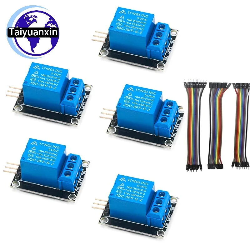
The KY-019 DC5V 1-channel Relay Module is a fundamental electronic switching component engineered for low-voltage control applications in hobbyist and educational microcontroller projects. This module provides a crucial interface, allowing microcontrollers like Arduino, Raspberry Pi, or PIC to safely control higher voltage and current loads. Its primary function is to provide galvanic isolation between the control circuit and the load circuit, a critical safety feature in any electrical system. This isolation prevents high voltage from damaging sensitive low-voltage electronics. It is a simple, effective solution.The visible components include a Tongling JQC-3FF-S-Z relay, a common and reliable electromechanical switch. This relay features a 5VDC coil, indicating its control voltage. The contacts are rated for 10A at 250VAC or 10A at 125VAC, which are substantial ratings for many common applications. These specifications are clearly printed on the relay itself, providing essential operational parameters. Understanding these limits is paramount.
This configuration implies that a low-power 5V signal from a microcontroller can energize the relay coil, thereby closing or opening the high-power contacts. This allows for the safe switching of devices such as lights, motors, or solenoids that operate at mains voltage or higher DC currents. The separation of control and load circuits is a cornerstone of electrical safety, preventing potential damage to the microcontroller and protecting the user. It is a robust design principle. Unlike direct transistor switching for DC loads, relays provide true galvanic isolation, making them inherently suitable for AC loads and situations where complete electrical separation is paramount. This makes the module a significant upgrade over rudimentary switching methods.
Module Architecture: Foundations of Reliable Switching
The module's design features a compact Printed Circuit Board (PCB) with clearly labeled screw terminals for the load side: Normally Open (NO), Common (COM), and Normally Closed (NC). These terminals are vital for secure and reliable connections to the high-current load. The control side includes standard header pins for VCC (5V power), GND (ground), and IN (input signal). An LED indicator is visibly present, signaling when the relay coil is energized. This provides immediate feedback.These screw terminals are essential for ensuring secure high-current connections, which significantly reduces the risk of arcing, loose connections, or accidental disconnections that could lead to electrical fires. Proper wire stripping and tightening of these terminals are critical steps in preventing electrical hazards. The quality of these connections directly impacts system reliability and safety. Secure connections are non-negotiable. Many DIY relay solutions often rely on less secure methods, such as soldering directly to relay pins or using flimsy connectors. This dedicated module, with its robust screw terminals, prioritizes secure connections, representing a substantial upgrade in terms of electrical integrity and safety for any project.
While not explicitly visible from all angles, modules of this type often incorporate an optocoupler for enhanced isolation between the microcontroller and the relay driver circuit. This additional layer of isolation further protects the sensitive digital electronics from electrical noise or voltage spikes originating from the load side. The PCB itself appears to be standard FR-4 material, offering adequate mechanical and electrical properties for its intended use. Component layout is logical. This attention to detail in the module's architecture contributes to its overall reliability and safety profile, making it a dependable choice for various electronic control tasks. It is a well-thought-out design.
Current and Voltage Thresholds: Operating Within Safe Parameters
The relay's specified ratings of 10A at 250VAC or 10A at 125VAC are crucial for safe operation. These figures represent the maximum current and voltage the relay contacts can reliably switch without degradation or failure. The 5VDC coil voltage is equally important, ensuring compatibility with common microcontroller power rails. Adhering to these limits is mandatory. Exceeding these limits can lead to several dangerous scenarios, including overheating of the relay contacts, welding of the contacts (preventing the circuit from opening), or even fire. Always verify the power requirements of the connected load against the relay's specifications. Under-specifying a relay is a common mistake.For instance, if controlling a 240V AC motor, the current draw of that motor must not exceed 10 amps. Similarly, for a 12V DC solenoid, the current must remain below 10 amps. The module's design, with its clearly marked ratings, empowers the user to make informed decisions regarding load management. This transparency is a safety feature. Proper calculation of inductive loads, which can generate significant back-EMF, is also important, often requiring additional protection circuitry like snubber networks or flyback diodes, though these are not part of the basic module. These considerations prevent premature relay failure. Compared to smaller signal relays, this 10A rating offers substantial switching capability, making it suitable for a wider range of applications, from controlling a desk lamp to a small pump. This versatility makes it a valuable asset in a hobbyist's toolkit.
Seamless Integration: Microcontroller Interfacing
The module features a single input pin (IN) for control, along with VCC and GND for power. This straightforward interface simplifies integration with microcontrollers. A simple digital HIGH or LOW signal from a microcontroller's GPIO pin is sufficient to toggle the relay's state. The visible LED indicator provides immediate visual feedback on the relay's activation status. This simplifies debugging. The 5V operating voltage of the coil ensures direct compatibility with most Arduino boards and many Raspberry Pi setups without requiring level shifters. This direct compatibility streamlines project development.For example, connecting the IN pin to a digital output pin on an Arduino allows for programmatic control of the relay. When the Arduino sets the pin HIGH, the relay activates; when set LOW, it deactivates. This ease of control is a significant advantage for rapid prototyping and educational purposes. The module's design minimizes external components. This direct digital control simplifies integration compared to driving a bare relay coil, which would necessitate additional driver circuitry such as a transistor and a flyback diode. The pre-assembled module saves time and reduces potential wiring errors, making it an ideal choice for beginners. It is truly plug-and-play for control signals.
Connectivity Essentials: The Role of Dupont Jumpers
The product package includes three pieces of 10CM 10-pin Dupont lines. These appear to be standard male-to-female or female-to-female jumper wires, commonly used in breadboarding and connecting development boards. These wires are crucial for establishing the necessary connections between the relay module and a microcontroller. They are highly convenient. The inclusion of these wires means users can immediately connect the relay module to their Arduino or Raspberry Pi without needing to source additional components. This enhances the out-of-box experience. The 10CM length is suitable for close-proximity connections within a project enclosure or on a breadboard.These wires facilitate quick and easy connections for the control signals (VCC, GND, IN) to the microcontroller. However, it is imperative to understand their limitations. The visible wire gauge of standard Dupont lines is typically light (e.g., 26-28 AWG), making them suitable only for signal and low-current power connections. They are not designed for the high-current load side of the relay. Using these wires for the 10A load circuit would pose a severe electrical hazard, risking overheating and fire. Always use appropriate gauge wiring for high-current applications. This is a critical safety distinction. Unlike the robust screw terminals on the relay module itself, these jumper wires are designed for temporary, low-power connections. For the high-voltage, high-current side of the relay, users must supply their own appropriately rated and insulated wiring, ensuring compliance with local electrical codes. This distinction is paramount for safety.
Rigorous Wiring: Ensuring Electrical Integrity
Proper installation and wiring practices are non-negotiable when working with relay modules, especially those switching AC mains voltage. The process involves connecting the 5VDC power to the VCC and GND pins, the control signal to the IN pin, and the load wires to the NO, COM, or NC terminals. Each connection must be secure. Before making any connections to the high-voltage load side, always ensure that the power source for the load is completely disconnected and de-energized. This prevents accidental shocks. Double-check all connections for tightness, correct polarity (for DC loads), and proper insulation. Loose connections are a leading cause of electrical faults and fires. A certified electrician always verifies connections.For the load connections, use appropriately sized and insulated wires that can safely handle the maximum current and voltage of the load. The wire gauge must be sufficient to prevent overheating. For example, a 10A load at 120V AC requires at least 16 AWG wire, and often 14 AWG for longer runs or higher safety margins. The insulation rating of the wire must also match or exceed the maximum voltage being switched. This ensures long-term safety. Neglecting these fundamental safety steps is a common pitfall in DIY electronics, leading to potential hazards that are easily avoidable with careful practice and adherence to electrical standards. This module provides the necessary terminals; the user must supply the correct wiring. This is where professional standards apply. Unlike casual signal wiring, high-voltage load wiring demands meticulous attention to detail and adherence to safety protocols, making the choice of wire gauge and insulation a critical design decision.
Component Resilience: Longevity in Prototyping
The Tongling JQC-3FF-S-Z relay is a widely recognized component in the hobbyist and educational electronics market. It is known for its general reliability and cost-effectiveness within its specified operational parameters. The PCB itself appears to be of standard quality, providing a stable platform for the components. While not designed for heavy industrial applications with continuous high-duty cycles, the module offers reasonable durability for intermittent or moderate use in prototyping and learning environments. Its lifespan is adequate for its intended purpose. The visible solder joints appear clean and well-formed, indicating a satisfactory manufacturing process. This contributes to the module's electrical integrity and mechanical stability. Good solder joints prevent intermittent failures.For applications requiring continuous operation, extreme environmental conditions, or switching highly inductive loads frequently, a more robust, industrial-rated relay with higher contact ratings and specialized features (e.g., arc suppression) would be necessary. However, for its intended niche—educational projects, home automation experiments, and general prototyping—this module provides excellent value and sufficient resilience. It is not an industrial workhorse. The design prioritizes accessibility and ease of use, making it an ideal entry point for those learning about relay control. Its component choices reflect a balance between performance, cost, and reliability for its target audience. This makes it a smart choice for beginners. Unlike premium industrial relays built for millions of cycles in harsh environments, this module offers a practical and economical solution for learning and experimentation, where occasional use and cost-efficiency are key considerations.