EARU Electric Optocoupler Relay Modules
Official Store Deal
Expert Analysis Overview
Precision Control with Optocoupled Relay Modules
The EARU Electric Relay Module is a critical electromechanical switching component engineered for precise control in low-voltage automation circuits. These modules are designed for integration into systems requiring isolated switching, such as those built around Arduino, PLC, or other automation equipment. The inclusion of an optocoupler is a significant design choice, ensuring electrical isolation between the control circuit and the load circuit. This isolation is paramount for protecting sensitive microcontrollers from voltage spikes or ground loops originating from higher-power loads.
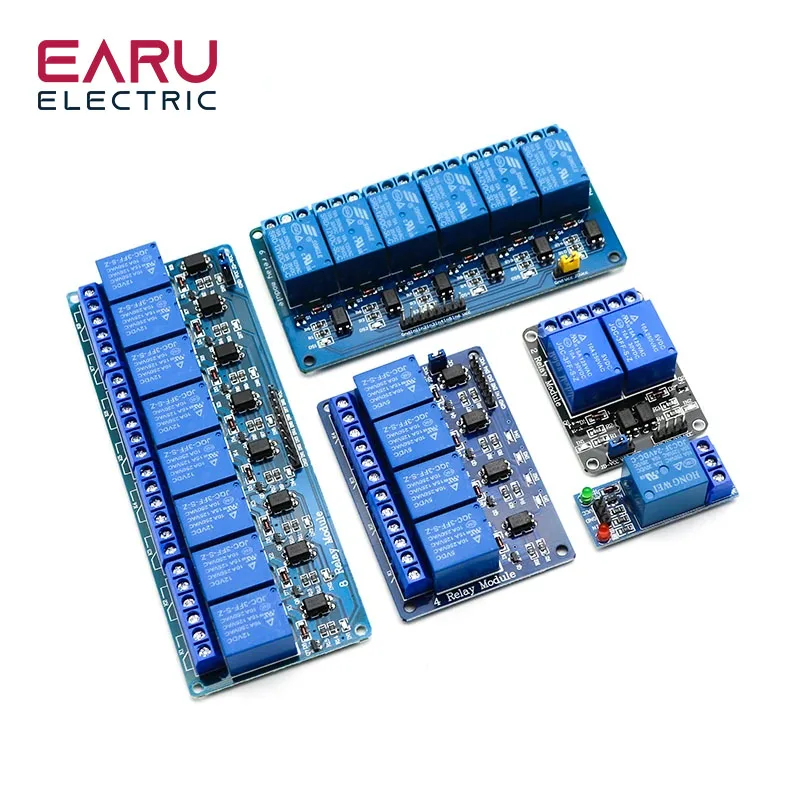
Multiple channel configurations are available, ranging from single-channel units to 16-channel boards. This scalability allows for flexible application across various project complexities. A single channel module is ideal for basic on/off control of one device. Larger boards, such as the 8-channel or 16-channel variants, facilitate the simultaneous management of multiple independent loads from a single control interface. This modularity simplifies system design and wiring.
Operating voltage options include 5V, 12V, and 24V, catering to diverse power supply requirements common in electronics and industrial control. The 5V modules are typically compatible with standard microcontroller logic levels. The 12V and 24V versions are often preferred in industrial settings where higher voltage control signals are prevalent. Each voltage variant maintains the core functionality and safety features.
Electrical Isolation and Safety Protocols
The integrated optocoupler provides galvanic isolation. This means there is no direct electrical connection between the input (control) side and the output (load) side. Light signals transmit the control command. This prevents high-voltage transients or noise from the load side from affecting the delicate control electronics. Such protection is vital for system longevity and operational reliability. Without optocouplers, a fault in the load circuit could potentially destroy the microcontroller.
Safety standards compliance is a primary concern for any electrical component. The visible 'HONG WEI' relays on the modules often carry UL or CE markings, indicating adherence to recognized safety specifications for electrical components. These certifications are not merely labels; they represent rigorous testing for insulation, dielectric strength, and operational integrity under specified conditions. Users should always verify the specific certifications for the exact relay model used. This ensures the component meets the necessary safety thresholds for the intended application.
Terminal quality directly impacts connection reliability and safety. The screw terminals visible on these modules appear robust, designed to secure wire connections firmly. Loose connections can lead to arcing, overheating, and potential fire hazards. Proper tightening of these terminals is essential for safe operation. The terminals are typically rated for specific wire gauges and current capacities. Exceeding these ratings can compromise the connection integrity and create unsafe conditions.
Load Handling and Current Capacity
Each relay is rated for specific current and voltage loads, typically 10A at 250VAC or 10A at 30VDC. These ratings define the maximum switching capacity of the relay contacts. Exceeding these limits can cause premature relay failure, contact welding, or even fire. It is imperative to match the relay's specifications to the actual load requirements. For inductive loads, such as motors or solenoids, derating the relay's current capacity is often recommended to account for inrush currents and back-EMF.
The visible wire gauge for the screw terminals appears suitable for the stated 10A rating. However, users must ensure their external wiring also matches or exceeds this capacity. Using undersized wires can lead to excessive heat generation and fire risk. Proper wire sizing is a fundamental principle of electrical safety. The module itself provides the switching mechanism. The external wiring carries the actual load current.
These modules are triggered at a low level, typically between 0 and 1.2V. This low-level trigger is common for direct interfacing with microcontroller GPIO pins. The VCC pin supplies the operating voltage for the relay coil and the module's internal circuitry. The GND pin provides the common ground reference. Understanding these input characteristics is crucial for correct wiring and preventing damage to the control source. Incorrect triggering can lead to erratic behavior or non-operation.
Versatility in Automation Applications
The versatility of these relay modules makes them suitable for a wide array of automation projects. Hobbyists can use them for home automation tasks, such as controlling lights or appliances with an Arduino. Industrial applications include controlling motors, solenoids, or heating elements in PLC-based systems. The ability to switch both AC and DC loads expands their utility significantly. This flexibility is a key advantage.
Unlike basic transistor switches, relays provide true electrical isolation and can handle significantly higher currents and voltages. This makes them indispensable for bridging the gap between low-power control logic and high-power loads. A direct connection between a microcontroller and a high-power device is unsafe and impractical. Relays offer a robust and reliable interface. They are a proven technology.
Consider a scenario where a user needs to control multiple 240V AC lights from a 5V Arduino. These relay modules provide the necessary interface, safely isolating the high AC voltage from the low-voltage microcontroller. The optocoupler ensures that even if a fault occurs on the AC side, the Arduino remains protected. This level of protection is non-negotiable in many applications. It prevents costly damage.
Installation and Operational Considerations
Installation involves connecting the control pins (IN) to the microcontroller's output, and the VCC and GND pins to the module's power supply. The load is then connected to the relay's common (COM), normally open (NO), and normally closed (NC) terminals. Clear labeling on the modules assists in correct wiring. Incorrect wiring can lead to non-functionality or damage. Always double-check connections before applying power.
For multi-channel modules, each relay operates independently. This allows for granular control over individual loads. The physical layout of the terminals is designed for straightforward wiring, even on the higher-channel count boards. Spacing between terminals is adequate for standard wire sizes. This design consideration aids in preventing accidental short circuits during installation. Proper wire stripping is also critical.
Regular inspection of connections is a good practice, especially in environments with vibration or temperature fluctuations. Over time, screw terminals can loosen. This can degrade performance and create safety hazards. A periodic check ensures continued secure connections. This proactive maintenance extends the lifespan of the module and the connected equipment. It also maintains safety.
Imagine a fully automated smart home system, where these relay modules seamlessly integrate with a central controller to manage lighting, heating, and security systems. The robust switching capability and critical electrical isolation ensure that your sensitive control electronics remain protected, providing peace of mind and reliable operation for years to come. This allows for complex automation without compromising safety or system integrity.