DSO183 Digital Oscilloscope DIY Kit
Official Store Deal
Expert Analysis Overview
Precision Signal Analysis for the Enthusiast
The DSO183 Digital Oscilloscope DIY Kit is an accessible, educational instrument designed for electronics students, hobbyists, and educators seeking a hands-on approach to understanding waveform analysis. This kit provides a foundational platform for practical training in electronic production, offering essential signal measurement capabilities within a compact form factor. Unlike fully assembled commercial units, the DSO183 emphasizes the learning process through its DIY construction, allowing users to gain intimate knowledge of oscilloscope principles from the ground up. Its design prioritizes ease of installation and stability, making it suitable for various experimental environments where reliable signal observation is paramount.
Core Metrological Capabilities
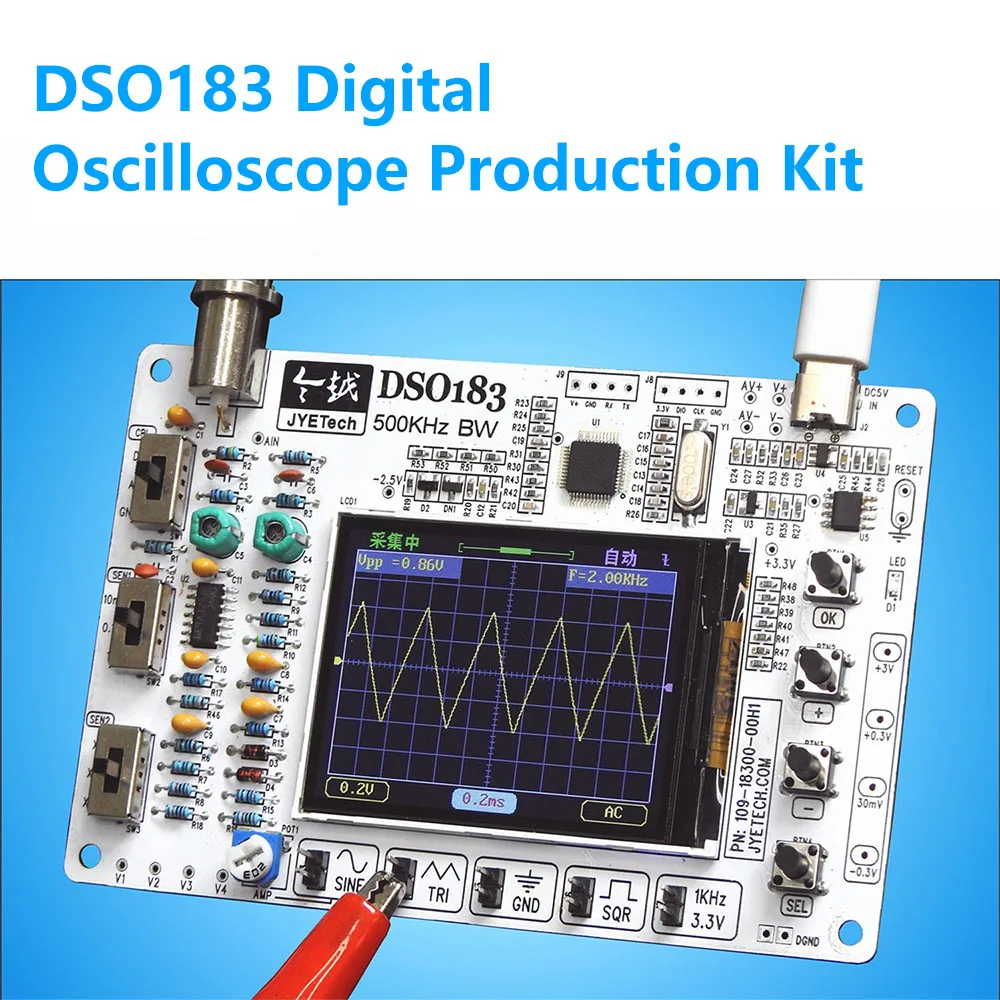
The DSO183 kit features a 500KHz high bandwidth, a critical specification for capturing a range of electrical signals. This bandwidth dictates the maximum frequency component of a signal that the oscilloscope can accurately display without significant attenuation. For instance, a 500KHz bandwidth allows for the precise visualization of signals up to approximately 50KHz, adhering to the common rule of thumb that an oscilloscope's bandwidth should be at least ten times the highest frequency component of the signal being measured for accurate representation. The visible display on the mainboard shows a clear, gridded waveform, indicating a graphical representation of voltage over time. This visual feedback is instantaneous.
The implication of this bandwidth is its utility in analyzing audio frequencies, power supply ripple, and various digital logic signals found in microcontrollers and basic communication protocols. It provides sufficient detail for debugging common electronic circuits, identifying noise, and verifying signal integrity in low to medium-frequency applications. The ability to discern subtle variations in waveform shape is crucial for effective troubleshooting. This instrument offers a clear window into circuit behavior.
Compared to basic multimeters, which only provide RMS or peak voltage readings, the DSO183 offers a dynamic, real-time visual representation of signal characteristics. This allows for the observation of transient events, signal distortion, and phase relationships, which are entirely invisible to a multimeter. While it does not compete with professional laboratory oscilloscopes boasting gigahertz bandwidths and advanced triggering, it significantly upgrades a hobbyist's diagnostic toolkit beyond simple voltage checks. It bridges a critical gap.
Educational Assembly and Structural Integrity
As a DIY loose parts kit, the DSO183 requires user assembly, which is a significant educational advantage. This hands-on construction process familiarizes the user with each component's function and placement on the printed circuit board (PCB). The kit's veneer structure design is highlighted for its convenient installation and high stability. This design approach suggests a layered construction that ensures components are securely mounted and the overall device maintains structural rigidity once assembled. Stability is key for repeatable measurements.
This assembly process directly contributes to a deeper understanding of electronic circuits and the internal workings of an oscilloscope. Users learn about soldering techniques, component identification, and the logical flow of signals through the instrument. Such practical engagement solidifies theoretical knowledge, transforming abstract concepts into tangible experience. It's a powerful learning tool.
Unlike pre-assembled units, where the internal architecture remains a black box, the DSO183's DIY nature demystifies the instrument. This transparency fosters a greater appreciation for the engineering involved and empowers users to potentially diagnose and repair issues within the oscilloscope itself, should they arise. It also provides a cost-effective entry point into owning an oscilloscope, as the labor component is shifted to the user. This makes advanced tools accessible.
Waveform Management and Signal Generation
The DSO183 supports waveform storage and quick retrieval functions, a valuable feature for comparative analysis and repeated use. This capability allows users to capture a specific waveform, save it to internal memory, and then recall it later for comparison against live signals or for detailed post-analysis. This is particularly useful when debugging intermittent faults or comparing the performance of different circuit configurations. Data logging is essential.
The implication of this feature is enhanced diagnostic efficiency. Instead of relying on memory or external photography, engineers can directly compare a known good waveform with a faulty one, quickly pinpointing deviations. This streamlines the troubleshooting process and improves the accuracy of fault isolation. It ensures consistent data points.
Furthermore, the kit includes a built-in signal generator, capable of outputting sine wave, triangle wave, and other waveform functions. This integrated generator eliminates the need for a separate piece of test equipment, providing a convenient source for injecting test signals into circuits. This allows users to actively stimulate a circuit and observe its response directly on the oscilloscope screen. It's a dual-purpose instrument.
Compared to purchasing a standalone function generator, the integrated solution offers significant cost savings and reduces bench clutter. For educational purposes, it provides an immediate means to demonstrate circuit responses to various input signals, reinforcing concepts like frequency response, amplification, and filtering. This combination of measurement and generation capability makes the DSO183 a comprehensive tool for basic electronics experimentation. It simplifies the setup.
Operational Simplicity and Accessibility
The DSO183 is described as easy to operate, positioning it as an ideal tool for electronics enthusiasts. Its user interface, visible on the small LCD screen, appears to feature intuitive controls and clear graphical representations of waveforms and settings. This focus on user-friendliness lowers the barrier to entry for individuals new to oscilloscopes or those who prefer a straightforward instrument for quick measurements. Simplicity enhances learning.
This ease of use means that beginners can quickly become proficient in basic oscilloscope operations without being overwhelmed by complex menus or an excessive number of controls. The learning curve is minimized, allowing users to focus more on understanding the signals they are measuring rather than struggling with the instrument itself. It accelerates practical application.
Compared to professional-grade oscilloscopes, which often feature extensive menus, multiple channels, and advanced triggering options that can be daunting for novices, the DSO183 offers a streamlined experience. Its design is tailored for educational and hobbyist applications where fundamental understanding and basic functionality are prioritized over advanced features. This makes it an excellent starting point for exploring the world of circuits. It's a gateway device.
Long-Term Utility and Value Proposition
The DSO183 Digital Oscilloscope DIY Kit, with its 0-500KHz bandwidth and Type-C interface, represents a significant value proposition for its target audience. The combination of hands-on assembly, fundamental measurement capabilities, waveform storage, and an integrated signal generator creates a versatile tool for ongoing learning and project development. Its DC 5V power requirement via a Type-C interface ensures broad compatibility with common power sources, including power banks, enhancing its portability and field use. This ensures sustained utility.
The long-term implication is that this kit serves as a durable educational asset. As users progress in their electronics journey, the foundational skills and understanding gained from building and operating this oscilloscope will remain invaluable. It supports continuous experimentation, from simple circuit analysis to more complex embedded systems debugging, within its specified frequency range. It grows with the user.
Unlike investing in a high-end oscilloscope that might be overkill for initial learning phases and significantly more expensive, the DSO183 offers a cost-effective entry into the world of precision measurement. Its focus on practical training and ease of use ensures that the investment yields substantial educational returns. Imagine confidently diagnosing circuit faults, visualizing signal integrity, and experimenting with various waveforms, all while deepening your understanding of electronics. This kit empowers you to transform theoretical knowledge into practical expertise, making complex circuit behaviors transparent and manageable. It's an investment in capability.
Technical Specifications Overview
Signal Acquisition and Display
The DSO183's 500KHz bandwidth is a critical parameter, defining its frequency response. This means signals with frequency components up to 500KHz can be observed, though accurate measurement typically requires the signal frequency to be well below this limit. The device's display, likely a color LCD, provides a clear visual grid for waveform interpretation, essential for precise amplitude and time measurements. The resolution of this display directly impacts the granularity of waveform detail. The waveform storage and recall function allows for capturing transient events or comparing signals over time, enhancing diagnostic capabilities. This ensures data integrity.
Integrated Functionality
An integrated signal generator is a notable inclusion, offering sine, triangle, and other waveform outputs. This eliminates the need for a separate function generator, streamlining the test setup for various experiments. The generator's output characteristics, such as amplitude and frequency range, are crucial for effective circuit stimulation. This adds significant value.
Power and Connectivity
The device operates on DC 5V power, supplied via a Type-C interface. This modern power input ensures compatibility with widely available power adapters and portable power banks, enhancing the instrument's versatility and mobility. The Type-C interface also suggests potential for data transfer or firmware updates, though specific capabilities would require further documentation. Power is universally accessible.
Physical and Educational Design
The veneer structure design promotes stability and ease of assembly, crucial for a DIY kit. This design choice implies a robust physical construction once assembled, minimizing mechanical flex that could affect measurement accuracy. As a DIY loose parts kit, it serves as a practical training tool, requiring hands-on construction. This fosters a deeper understanding of electronic principles. It's a learning experience.
Operational Guidance
Initial Assembly and Power-Up
Carefully follow the provided assembly instructions, ensuring all components are correctly oriented and soldered. Verify all connections before applying power. Connect the DSO183 to a stable DC 5V power source via the Type-C interface. Observe the initial boot sequence on the LCD screen. A stable power supply is critical.
Basic Waveform Acquisition
Connect the probe to the input BNC connector and the circuit under test. Adjust the vertical (voltage) and horizontal (time) scales using the onboard controls to bring the waveform into view. Utilize the trigger settings to stabilize the waveform on the display. Practice with known signals first.
Utilizing the Signal Generator
Access the built-in signal generator function through the menu. Select the desired waveform type (sine, triangle) and adjust its frequency and amplitude. Connect the generator's output to a test circuit to observe its response on the oscilloscope input. This allows for active circuit testing.
Waveform Storage and Recall
Once a stable waveform is displayed, navigate to the storage menu to save the current waveform. To compare, recall a previously saved waveform and display it alongside a live signal. This feature is invaluable for identifying subtle changes or deviations in circuit behavior. Compare and contrast signals.
Calibration and Accuracy Checks
Periodically verify the oscilloscope's accuracy using a known, stable reference signal, such as a precision voltage source or a crystal oscillator. Check the amplitude and frequency readings against the reference. While a DIY kit may not offer certified calibration, regular checks ensure consistent performance. Consistency is paramount.