Digital Time Delay Relay Module
Official Store Deal
Expert Analysis Overview
Precision Automation: An Electrician's Review of the Digital Time Delay Relay Module
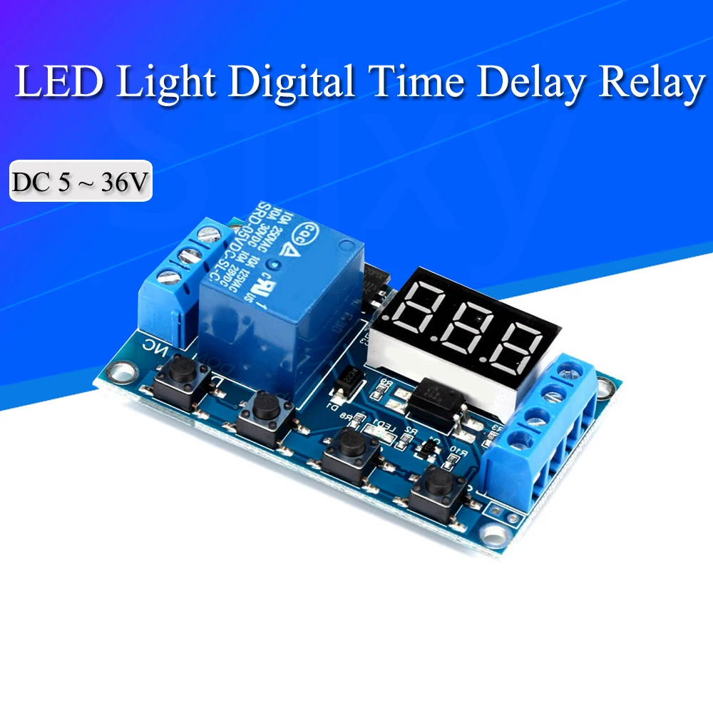
The LED Light Digital Time Delay Relay is a versatile, compact timing control module engineered for precise automation in low-voltage DC circuits. This device presents itself as a fundamental component for hobbyists and professionals seeking to implement timed switching functions without the complexity of microcontrollers or the limitations of purely analog solutions. Its design prioritizes straightforward integration and reliable operation within a broad spectrum of electrical projects. The module's visible components and specified operating parameters indicate a focus on functional utility and adaptability across various DC voltage applications.
Core Functionality: Precision Timing and Control
The module's most prominent feature is its 3-digit 7-segment LED display, providing clear, real-time feedback on timing parameters. This visual interface is critical for accurate setup and monitoring of delay sequences. Users can precisely set delay times. The display ensures operational transparency. Unlike older, less precise analog timers that rely on potentiometers and RC circuits, this digital implementation offers granular control, typically down to 0.1-second increments, across a wide range up to 999 minutes. This level of precision is indispensable for applications requiring consistent and repeatable timing, such as sequential process control or automated lighting systems. The digital nature inherently reduces drift and improves accuracy over time, a significant advantage in industrial or critical timing scenarios where consistency is paramount.
The onboard tactile push buttons—labeled SET, STOP, UP, and DOWN—facilitate intuitive interaction with the module. These buttons allow for direct programming of timing modes and delay values without external programming tools. This direct interface simplifies field adjustments. The user experience is streamlined, enabling quick modifications to timing parameters as project requirements evolve. Compared to modules requiring serial communication or complex software interfaces, this direct button control minimizes setup time and reduces the potential for configuration errors, making it accessible even to those with limited programming experience. This direct control is a clear benefit.
Power Delivery and Circuit Integrity
Powering the module is flexible, supporting a wide operating voltage range of DC 5V to 36V. This broad compatibility allows the module to be integrated into diverse systems, from 5V USB-powered prototypes to 12V automotive applications or 24V industrial control panels. The module accepts power via two distinct methods: a Micro-USB port and screw terminal blocks. The Micro-USB option offers convenient power sourcing from standard USB chargers or power banks, ideal for prototyping and portable applications. This simplifies initial testing. The screw terminals, conversely, provide a more robust and permanent connection for embedded installations, ensuring secure power delivery in environments where vibration or movement might compromise less secure connections. Proper terminal tightening is essential.
The input terminals are clearly labeled, indicating positive and negative connections. Adhering to correct polarity is non-negotiable for preventing damage to the module. The visible traces on the PCB suggest adequate copper weight for the specified current draw of the control circuit itself, which is typically low. Unlike modules with fixed voltage inputs, this wide range reduces the need for external voltage regulators, simplifying the overall circuit design and bill of materials for many projects. This adaptability saves time and components.
Relay Mechanism and Load Management
At the heart of this timing module is a single-channel electromechanical relay, specifically identified as a Songle SRD-05VDC-SL-C. This relay is visibly rated for 10 Amperes at 250VAC or 10 Amperes at 30VDC. These ratings are crucial for determining the maximum load the module can safely switch. The relay provides galvanic isolation between the control circuit and the switched load, a fundamental safety feature in electrical engineering. This isolation prevents high-voltage or high-current loads from affecting the sensitive control electronics. It protects the user and the control module.
The 10A current rating means the module can directly control a variety of DC loads, such as LED lighting arrays, small DC motors, solenoid valves, or heating elements, provided their current draw does not exceed 10A. For AC applications, while the relay itself is rated for 250VAC, the module's primary control input is DC. Therefore, extreme caution and expert knowledge are required if attempting to switch AC loads, ensuring proper insulation and safety protocols are strictly followed. Overloading the relay is a significant fire hazard. Unlike solid-state relays (SSRs) which offer faster switching and no moving parts, this electromechanical relay provides true open-circuit isolation when de-energized, which can be advantageous in certain safety-critical applications. However, electromechanical relays have a finite number of operations before wear becomes an issue.
Triggering and Operational Modes
Beyond simple timed delays, the module incorporates a dedicated trigger input, allowing external events to initiate the timing sequence. This trigger can be a momentary switch, a sensor output, or a signal from another control system. This enhances automation flexibility. The presence of a trigger input transforms the module from a basic timer into a responsive control element, capable of reacting to environmental changes or user commands. For instance, a motion sensor could trigger a light to stay on for a set duration, or a push button could start a cycle of operations.
While specific operational modes are not explicitly detailed on the visible PCB, similar modules typically offer various functions such as: delay-on, delay-off, cycle timing (repeating on/off), and trigger-activated modes. These modes are usually configurable via the SET button and displayed on the LED. The ability to select different modes makes the module highly adaptable. This versatility allows the module to address a wide array of automation challenges, from simple timed events to more complex, repetitive processes. It offers significant capability. Compared to fixed-function timers, this module's programmable modes provide a substantial upgrade in utility and application scope, reducing the need for multiple specialized timers.
Physical Construction and Durability Considerations
The module is constructed on a blue printed circuit board (PCB), typical for low-cost electronic components. The PCB appears to be of standard FR-4 material, offering adequate mechanical stability for its intended use. Component placement is logical, with the digital display, relay, buttons, and terminal blocks arranged for ease of access and wiring. The solder joints, as visible in the images, appear clean and consistent, suggesting a reasonable level of manufacturing quality. Good soldering is crucial for reliability. The open circuit board design, while cost-effective and compact, means the module lacks inherent protection against dust, moisture, or physical impact. Users must provide an appropriate enclosure for the module if it is to be deployed in anything other than a controlled, indoor environment. This is a necessary consideration for longevity.
The screw terminal blocks are a critical interface for power and load connections. Their robust design ensures wires are held securely, minimizing the risk of intermittent connections or accidental dislodgement. Proper wire stripping and insertion are vital. The terminals are clearly marked for input power (GND, +5V, 6.0-30.0V, GND_T, Trigger) and relay output (NO, COM, NC). These markings are essential for correct wiring. Unlike spring-clip terminals, screw terminals provide a high-pressure contact that is less prone to loosening over time, especially in applications with minor vibrations. The quality of these terminals directly impacts the safety and reliability of the entire circuit. Always double-check connections.
Installation and Safety Protocols
As a Certified Electrician, the paramount concern with any electrical component is safety. The clear labeling of input and output terminals is a good starting point for safe installation. Users must meticulously follow these labels to prevent miswiring, which can lead to component damage, short circuits, or even fire. The input voltage range (DC 5-36V) must be strictly adhered to. Exceeding this range will destroy the module. Similarly, the relay's current rating of 10A is an absolute limit. Connecting loads that draw more than 10A will cause the relay contacts to overheat, potentially welding them shut or causing a fire. Always calculate load current carefully.
Proper wire gauge selection is also critical. For 10A loads, wires should be appropriately sized to prevent excessive voltage drop and overheating. For example, 18 AWG wire is generally suitable for 10A at short distances, but longer runs or higher currents require thicker gauges. All connections must be tight and insulated. Exposed wires are a shock hazard. The module's open PCB design necessitates an enclosure to protect against accidental contact with live components and environmental factors. This is not a plug-and-play device for untrained individuals. Understanding basic electrical principles is a prerequisite for safe and effective use of this module. This ensures operational integrity.
Value Proposition and Application Scenarios
This digital time delay relay module offers significant value for its price point, especially for DIY enthusiasts, students, and professionals developing custom automation solutions. Its low cost makes it an accessible entry point into timed control. The module's capability to handle a wide voltage range and moderate current loads, combined with precise digital timing and trigger functionality, positions it as a versatile tool. It enables projects that would otherwise require more complex or expensive programmable logic controllers (PLCs) for simple timing tasks. The investment in this module is quickly recouped through its utility and the avoidance of more costly alternatives. It is a cost-effective solution.
Imagine automating a chicken coop door to open at sunrise and close at sunset, triggered by a light sensor and timed for specific durations. Consider a hydroponic system where pumps and lights need to cycle on and off at precise intervals throughout the day. Envision a security system where a motion detector triggers a floodlight for a set period. This module provides the foundational timing logic for all these scenarios and more, empowering users to bring their automation ideas to life with reliability and precision. The possibilities are extensive.
Conclusion: Empowering Precise Automation
This digital time delay relay module stands as a robust and highly adaptable component for a multitude of DC automation projects. Its combination of wide voltage compatibility, precise digital timing, and a capable electromechanical relay makes it an excellent choice for those needing reliable timed switching. The intuitive button interface simplifies configuration, while the clear LED display ensures operational transparency. For anyone looking to implement accurate, trigger-activated timing in their electrical designs, this module provides a cost-effective and efficient solution. Imagine the satisfaction of seeing your custom automation project function flawlessly, precisely controlling devices with the reliability this module offers, freeing up your time and enhancing efficiency in your daily operations.