DC Motor PWM Adjustable Speed Controller
Official Store Deal
Expert Analysis Overview
The DC Motor PWM Adjustable Speed Controller is a compact, cost-effective electronic module designed for precise regulation of direct current motor speeds, targeting hobbyists and small-scale automation projects. This board leverages Pulse Width Modulation to offer variable output, making it suitable for applications where fine control over motor RPM is critical. Its minimalist design and clear terminal markings simplify integration into existing low-voltage circuits.
Compared to more industrial-grade controllers, this unit prioritizes miniaturization and accessibility over heavy-duty power handling or advanced protection features. Its simplicity is a core attribute. The board's layout appears logical, with power input and motor output terminals clearly segregated from the control potentiometer, minimizing potential interference paths. The use of surface-mount technology (SMT) allows for higher component density, contributing to the board's small size. This is a practical design. The visible integrated circuits (ICs) are likely a dedicated PWM controller chip and a power MOSFET, forming the heart of the speed regulation mechanism. These components are chosen for their efficiency in switching applications.
Maintaining clean signal transmission is vital for PWM controllers. The rapid switching involved in PWM can generate electrical noise, which must be contained. The board's compact design inherently limits the length of conductors that could act as antennas for this noise. For low-power applications, this passive approach is often sufficient. The integrity of the power path directly impacts motor performance. A clean, stable power supply is fundamental.
Unlike controllers designed for higher current applications that might feature thicker copper layers, multiple ground planes, or dedicated heat sinks, this module relies on its low current rating to manage thermal dissipation passively. For its intended use, this is an acceptable trade-off. The visible ICs, likely a PWM generator and a MOSFET driver, are standard components for such applications, offering reliable switching performance. Their small size helps with thermal management at low currents. This is a sensible design choice for the target market.
Reliable connections are fundamental to any electrical circuit, particularly those involving motors that can induce vibration. The screw-down mechanism of these terminals provides a robust physical and electrical contact, minimizing the chance of wires shaking loose due to vibration or accidental tugs. This design choice enhances long-term reliability. Loose connections can cause intermittent operation, arcing, or even complete circuit failure. Assessing long-term reliability of connections is crucial for any project. The visible metal inserts within the plastic housing suggest a durable connection point.
Compared to soldered connections, which require specialized tools and skills, or less secure push-in terminals, screw terminals offer a balance of convenience and security, particularly for users who may need to frequently connect and disconnect wires during prototyping or testing phases. The visible plastic housing of the terminal block appears sturdy enough for its purpose, preventing accidental short circuits between adjacent terminals. This contributes to overall project safety. The ability to quickly and securely connect wires without soldering is a significant advantage for hobbyists.
The tactile feedback of a physical knob offers intuitive control, allowing for fine adjustments to motor speed that might be more challenging with digital interfaces. Precision of control is a key benefit. Users can quickly dial in the desired RPM without navigating complex menus or pressing multiple buttons. The continuous rotation of the knob allows for very granular adjustments, which is often necessary for applications requiring specific operating speeds.
Unlike controllers with push-button or digital up/down controls, the analog nature of the potentiometer provides a continuous range of adjustment, which is often preferred for applications requiring smooth transitions in speed, such as dimming an LED or gradually accelerating a small fan. The visible "104" marking on the potentiometer body indicates a 100k Ohm resistance, a common value for such control applications, providing a suitable range for the PWM circuit to achieve full speed variation. This is a standard component.
Ease of integration is a significant advantage for hobbyists and makers. A securely mounted board reduces strain on wiring and components, contributing to the overall longevity of the project. The small size means it can fit into tight spaces, making it ideal for compact designs where every millimeter counts. This modularity is valuable.
Compared to larger, enclosed motor controllers, this bare PCB module offers maximum flexibility for custom enclosures and mounting solutions. The 15mm height of the potentiometer shaft, as indicated in one image, provides ample clearance for a control knob to extend through a panel, ensuring ergonomic operation. This allows for a clean finish. The standardized mounting hole pattern simplifies integration into common project boxes or custom-fabricated panels.
Understanding these ratings is critical for safe and effective operation. Exceeding the 2A current limit, even momentarily, can lead to overheating of the MOSFETs and other components, potentially causing permanent damage to the controller. The low voltage operation is particularly useful for battery-powered devices where efficiency and minimal power consumption are key. Operating within specifications is vital.
Unlike higher-power industrial motor drivers that can handle tens or hundreds of amps and often require substantial heat sinking, this module is clearly positioned for light-duty applications. Its 2A rating is ideal for small fans, pumps, robotic actuators, model trains, or other small electromechanical devices. Users must verify their motor's current draw before connecting it to this controller to prevent premature failure. This is a critical pre-flight check.
Proper thermal conditions directly impact the longevity of electronic components. Operating within specified limits and ensuring good airflow will significantly extend the lifespan of the controller. Overheating can lead to component degradation, reduced performance, and eventual failure. This simple precaution ensures a longer service life.
In contrast to passively cooled designs, active cooling (like a small fan) would be overkill for this low-power module, but environmental considerations are still important. Mounting the board away from other heat-generating components or in a well-ventilated area will help maintain optimal operating temperatures. The robustness of the components at their rated current is key. For applications where the motor might stall or experience momentary current spikes, it is advisable to operate the controller below its maximum continuous rating to provide a safety margin.
Consider its application in a miniature robot for controlling drive motors, a variable-speed fan for a custom cooling solution in a small enclosure, or a small pump for a hydroponics system where flow rate needs adjustment. The ability to precisely adjust motor speed opens up many possibilities for optimizing performance and energy consumption in these scenarios. It offers granular control. This flexibility enhances project functionality.
Unlike complex motor drivers that require microcontrollers and programming, this module provides a direct, hardware-based solution for speed control, simplifying the project design process. Its plug-and-play nature reduces development time and complexity, making it accessible to a wider audience. The clear wiring diagrams provided in the product images further streamline integration, ensuring a smooth setup experience.
The low cost also means that if a component fails due to misuse or accidental damage, replacing the entire module is often more economical and less time-consuming than troubleshooting and repairing individual parts. This reduces downtime and the need for specialized repair skills. It's a disposable component in the best sense, prioritizing quick replacement over intricate repair.
Compared to proprietary or integrated motor control solutions, this standalone module provides a flexible and budget-friendly alternative. Its widespread availability ensures easy replacement if needed, preventing project delays and keeping project costs low. The ability to source such a specific function at a minimal investment empowers makers to experiment and innovate without financial barriers.
For long-term reliability, ensuring the connections to the screw terminals are tight and that the module is protected from environmental factors like moisture and dust is important. Periodic inspection of connections can prevent issues arising from vibration or thermal cycling. This minimal maintenance ensures consistent performance over time. A protective enclosure is highly recommended.
Unlike more complex systems that might require firmware updates or intricate calibration, this hardware-based controller operates consistently once installed and configured. Its "set-and-forget" nature is a distinct advantage for many applications where reliability and simplicity are paramount. This controller is a workhorse, designed for straightforward operation without ongoing adjustments. It just works.
Imagine a scenario where a small, custom-built ventilation system needs precise airflow adjustments throughout the day; this controller seamlessly integrates, allowing for quiet operation at night and increased circulation during peak hours, all managed with a simple turn of a knob. This level of adaptable control enhances the functionality and user experience of any low-power DC application, ensuring optimal performance without unnecessary complexity or expense. It empowers creators.
Under the Hood: Component Selection and Layout
The visible green PCB, measuring approximately 32mm by 32mm, houses a straightforward yet functional circuit. Surface-mount components dominate the board, indicating a modern manufacturing process that allows for its compact footprint. A single electrolytic capacitor is prominently featured, likely serving as a smoothing capacitor for the input power or output to the motor, crucial for stable operation. This component selection implies a design optimized for cost-efficiency and space-saving, typical for modules intended for hobbyist use or integration into larger, budget-conscious systems. The capacitor's presence suggests an attempt to mitigate voltage ripple, which can otherwise lead to erratic motor behavior or premature wear. Stable power delivery is paramount. Without proper filtering, the pulsed DC output from the PWM circuit could introduce noise into the system, potentially affecting other sensitive electronics in the same project. This small component plays a critical role.Compared to more industrial-grade controllers, this unit prioritizes miniaturization and accessibility over heavy-duty power handling or advanced protection features. Its simplicity is a core attribute. The board's layout appears logical, with power input and motor output terminals clearly segregated from the control potentiometer, minimizing potential interference paths. The use of surface-mount technology (SMT) allows for higher component density, contributing to the board's small size. This is a practical design. The visible integrated circuits (ICs) are likely a dedicated PWM controller chip and a power MOSFET, forming the heart of the speed regulation mechanism. These components are chosen for their efficiency in switching applications.
Signal Integrity and Power Path
The traces on the PCB, while not visible in extreme detail, appear to be of adequate width for the specified 2A current rating. Proper trace width is essential for minimizing resistive losses and preventing overheating, especially in continuous operation where even small resistances can generate significant heat. The compact nature of the board means shorter trace lengths, inherently reducing potential electromagnetic interference (EMI) in close-proximity applications. This helps ensure clean signal transmission. Any noise on the control signal or power lines can translate into jittery motor performance, audible hum, or even reduced motor lifespan. The design, with its dedicated power and motor terminals, aims to keep these paths distinct, contributing to cleaner operation. This separation helps prevent cross-talk.Maintaining clean signal transmission is vital for PWM controllers. The rapid switching involved in PWM can generate electrical noise, which must be contained. The board's compact design inherently limits the length of conductors that could act as antennas for this noise. For low-power applications, this passive approach is often sufficient. The integrity of the power path directly impacts motor performance. A clean, stable power supply is fundamental.
Unlike controllers designed for higher current applications that might feature thicker copper layers, multiple ground planes, or dedicated heat sinks, this module relies on its low current rating to manage thermal dissipation passively. For its intended use, this is an acceptable trade-off. The visible ICs, likely a PWM generator and a MOSFET driver, are standard components for such applications, offering reliable switching performance. Their small size helps with thermal management at low currents. This is a sensible design choice for the target market.
Terminal Durability and Connection Reliability
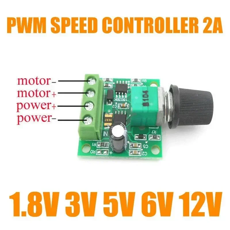
The module features a 4-pin screw terminal block for power input and motor output connections. These green terminals are a common choice for their ease of use and secure wire retention, providing a robust mechanical and electrical interface. Each terminal is clearly labeled: "motor-", "motor+", "power+", and "power-", which significantly aids in correct wiring and reduces the risk of misconnection, a common pitfall for beginners. This clarity is a major benefit.Reliable connections are fundamental to any electrical circuit, particularly those involving motors that can induce vibration. The screw-down mechanism of these terminals provides a robust physical and electrical contact, minimizing the chance of wires shaking loose due to vibration or accidental tugs. This design choice enhances long-term reliability. Loose connections can cause intermittent operation, arcing, or even complete circuit failure. Assessing long-term reliability of connections is crucial for any project. The visible metal inserts within the plastic housing suggest a durable connection point.
Compared to soldered connections, which require specialized tools and skills, or less secure push-in terminals, screw terminals offer a balance of convenience and security, particularly for users who may need to frequently connect and disconnect wires during prototyping or testing phases. The visible plastic housing of the terminal block appears sturdy enough for its purpose, preventing accidental short circuits between adjacent terminals. This contributes to overall project safety. The ability to quickly and securely connect wires without soldering is a significant advantage for hobbyists.
Control Interface Analysis
The Potentiometer: User Interaction and Precision
A black rotary potentiometer with a knurled knob serves as the primary user interface for speed adjustment. This component is responsible for varying the duty cycle of the PWM signal, directly controlling the motor's average voltage and thus its speed. The potentiometer is panel-mounted, suggesting it can be easily integrated into an enclosure, with the shaft extending through a front panel for user access. This provides direct control.The tactile feedback of a physical knob offers intuitive control, allowing for fine adjustments to motor speed that might be more challenging with digital interfaces. Precision of control is a key benefit. Users can quickly dial in the desired RPM without navigating complex menus or pressing multiple buttons. The continuous rotation of the knob allows for very granular adjustments, which is often necessary for applications requiring specific operating speeds.
Unlike controllers with push-button or digital up/down controls, the analog nature of the potentiometer provides a continuous range of adjustment, which is often preferred for applications requiring smooth transitions in speed, such as dimming an LED or gradually accelerating a small fan. The visible "104" marking on the potentiometer body indicates a 100k Ohm resistance, a common value for such control applications, providing a suitable range for the PWM circuit to achieve full speed variation. This is a standard component.
Integration and Mounting Considerations
The compact dimensions of the PCB (32mm x 32mm) make it highly versatile for integration into various projects. Four mounting holes, one at each corner, are visible, allowing for secure attachment to a chassis or project box using small screws. This physical stability is important for preventing damage from movement or vibration, which can stress solder joints and component leads. A secure mount is essential.Ease of integration is a significant advantage for hobbyists and makers. A securely mounted board reduces strain on wiring and components, contributing to the overall longevity of the project. The small size means it can fit into tight spaces, making it ideal for compact designs where every millimeter counts. This modularity is valuable.
Compared to larger, enclosed motor controllers, this bare PCB module offers maximum flexibility for custom enclosures and mounting solutions. The 15mm height of the potentiometer shaft, as indicated in one image, provides ample clearance for a control knob to extend through a panel, ensuring ergonomic operation. This allows for a clean finish. The standardized mounting hole pattern simplifies integration into common project boxes or custom-fabricated panels.
Power Handling Capabilities
Voltage Range and Current Capacity
The controller is explicitly rated for a wide input voltage range, from 1.8V to 15V DC, and a maximum continuous current of 2A. This broad voltage compatibility makes it suitable for a variety of low-voltage DC motors, from small hobby motors powered by AA batteries (e.g., 3V) to slightly larger motors running on 12V or 15V power supplies. Versatility is a strong point. This wide range means fewer specialized controllers are needed for different projects.Understanding these ratings is critical for safe and effective operation. Exceeding the 2A current limit, even momentarily, can lead to overheating of the MOSFETs and other components, potentially causing permanent damage to the controller. The low voltage operation is particularly useful for battery-powered devices where efficiency and minimal power consumption are key. Operating within specifications is vital.
Unlike higher-power industrial motor drivers that can handle tens or hundreds of amps and often require substantial heat sinking, this module is clearly positioned for light-duty applications. Its 2A rating is ideal for small fans, pumps, robotic actuators, model trains, or other small electromechanical devices. Users must verify their motor's current draw before connecting it to this controller to prevent premature failure. This is a critical pre-flight check.
Thermal Management and Longevity
Given the 2A current rating and the absence of a dedicated heat sink, the thermal management relies primarily on the PCB's copper traces and the surface area of the components themselves. For continuous operation at or near the maximum current, adequate ventilation within the enclosure is recommended to prevent excessive temperature buildup. Heat is the enemy of electronics, accelerating component degradation.Proper thermal conditions directly impact the longevity of electronic components. Operating within specified limits and ensuring good airflow will significantly extend the lifespan of the controller. Overheating can lead to component degradation, reduced performance, and eventual failure. This simple precaution ensures a longer service life.
In contrast to passively cooled designs, active cooling (like a small fan) would be overkill for this low-power module, but environmental considerations are still important. Mounting the board away from other heat-generating components or in a well-ventilated area will help maintain optimal operating temperatures. The robustness of the components at their rated current is key. For applications where the motor might stall or experience momentary current spikes, it is advisable to operate the controller below its maximum continuous rating to provide a safety margin.
Application and Value Proposition
Ideal Use Cases and Project Suitability
This PWM speed controller is perfectly suited for a range of DIY electronics projects, educational kits, and small-scale automation tasks. Its simplicity and low cost make it an excellent choice for beginners learning about motor control or for experienced makers needing a quick, reliable solution for a specific function. Small projects benefit greatly from its straightforward implementation.Consider its application in a miniature robot for controlling drive motors, a variable-speed fan for a custom cooling solution in a small enclosure, or a small pump for a hydroponics system where flow rate needs adjustment. The ability to precisely adjust motor speed opens up many possibilities for optimizing performance and energy consumption in these scenarios. It offers granular control. This flexibility enhances project functionality.
Unlike complex motor drivers that require microcontrollers and programming, this module provides a direct, hardware-based solution for speed control, simplifying the project design process. Its plug-and-play nature reduces development time and complexity, making it accessible to a wider audience. The clear wiring diagrams provided in the product images further streamline integration, ensuring a smooth setup experience.
Cost-Effectiveness and Repair Potential
At its price point, this controller represents exceptional value for money, especially when considering the cost of individual components and the effort required to build a similar circuit from scratch. It offers an affordable way to add variable speed control to existing equipment or new builds without a significant financial outlay. Fixing expensive equipment with affordable components is a smart strategy. This makes repairs accessible.The low cost also means that if a component fails due to misuse or accidental damage, replacing the entire module is often more economical and less time-consuming than troubleshooting and repairing individual parts. This reduces downtime and the need for specialized repair skills. It's a disposable component in the best sense, prioritizing quick replacement over intricate repair.
Compared to proprietary or integrated motor control solutions, this standalone module provides a flexible and budget-friendly alternative. Its widespread availability ensures easy replacement if needed, preventing project delays and keeping project costs low. The ability to source such a specific function at a minimal investment empowers makers to experiment and innovate without financial barriers.
Long-Term Reliability and Maintenance
The design's simplicity contributes to its inherent reliability. Fewer components mean fewer points of failure, which is a significant advantage in any electronic circuit. The visible soldering points appear clean and well-formed, suggesting good manufacturing quality for a mass-produced item. Clean soldering is crucial for electrical integrity and mechanical strength. This indicates a well-assembled product.For long-term reliability, ensuring the connections to the screw terminals are tight and that the module is protected from environmental factors like moisture and dust is important. Periodic inspection of connections can prevent issues arising from vibration or thermal cycling. This minimal maintenance ensures consistent performance over time. A protective enclosure is highly recommended.
Unlike more complex systems that might require firmware updates or intricate calibration, this hardware-based controller operates consistently once installed and configured. Its "set-and-forget" nature is a distinct advantage for many applications where reliability and simplicity are paramount. This controller is a workhorse, designed for straightforward operation without ongoing adjustments. It just works.
Imagine a scenario where a small, custom-built ventilation system needs precise airflow adjustments throughout the day; this controller seamlessly integrates, allowing for quiet operation at night and increased circulation during peak hours, all managed with a simple turn of a knob. This level of adaptable control enhances the functionality and user experience of any low-power DC application, ensuring optimal performance without unnecessary complexity or expense. It empowers creators.