DC 5V-36V Trigger Cycle Delay Timer Relay Module
Official Store Deal
Expert Analysis Overview
The DC 5V-36V Trigger Cycle Delay Timer Relay Module is a compact, programmable timing control unit engineered for precise automation tasks in low-voltage DC circuits. This module addresses the common challenge of integrating timed operations into existing electronic systems without requiring complex microcontroller programming. Its design prioritizes ease of use and broad compatibility, making it a valuable asset for electronics repair technicians and hobbyists alike.
The module features a 3-digit LED display for clear visual feedback of timing parameters and operational status. This display is bright. Users can easily monitor current settings or countdowns, which is critical for debugging and verification. The visible display contrasts sharply with modules relying solely on potentiometers or dip switches, which often lack real-time feedback and precise numerical adjustment.
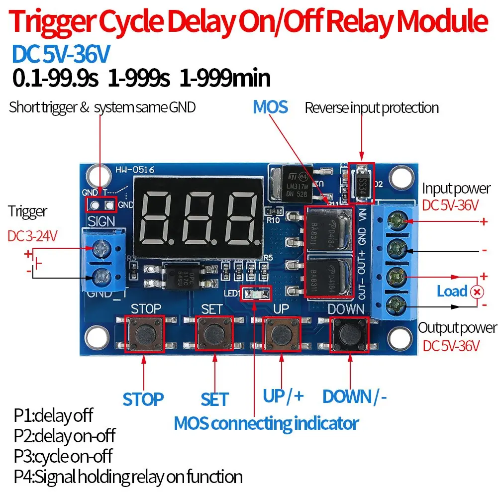
Parameter adjustment is managed via four tactile push buttons: STOP, SET, UP/+, and DOWN/-. These controls facilitate intuitive navigation through the module's various operating modes and time settings. The tactile feedback of these buttons ensures positive engagement, reducing the chance of accidental adjustments during setup. This direct interface simplifies configuration significantly.
Compared to basic analog timers, this digital interface provides superior accuracy and repeatability. Analog timers often drift. This module maintains consistent timing cycles, crucial for applications requiring exact delays or intervals.
Power input to the module is flexible, accepting a wide DC voltage range from 5V to 36V. This broad compatibility means it can be integrated into various systems, from small battery-powered projects to 24V industrial control panels. The module's ability to operate across such a voltage spectrum reduces the need for external voltage regulators, streamlining system design. It draws minimal current.
The trigger input supports a DC voltage range of 3V to 24V, allowing activation from diverse signal sources, including microcontrollers, push buttons, or other sensors. This flexibility in trigger voltage ensures seamless integration with most common logic levels. A short trigger pulse is sufficient.
Output control is handled by a MOSFET (Metal-Oxide-Semiconductor Field-Effect Transistor), indicated by the 'MOS connecting indicator' on the PCB. This is a significant design choice. MOSFETs are ideal for switching DC loads, offering silent operation, high switching speeds, and excellent longevity compared to traditional mechanical relays, which can wear out or generate audible clicks. The output also supports a DC voltage range of 5V-36V, matching the input power. This allows direct switching of loads like motors, LEDs, or solenoids within the specified voltage and current limits.
Unlike modules with mechanical relays, the MOSFET output eliminates contact bounce and arc erosion. This enhances reliability. It also means the module is suitable for applications where noise is a concern.
The module offers several programmable operating modes, clearly labeled as P1 through P4 in the accompanying diagrams. These modes define the module's behavior in response to a trigger signal:
P1: Delay Off. Upon receiving a trigger, the output turns on for a set duration, then turns off. This is useful for timed lighting or cooling fans. This mode is straightforward. P2: Delay On-Off. The output remains off for a set delay after the trigger, then turns on for another set duration, and finally turns off. This sequence is valuable for staggered system startups or sequential process control. It adds a pre-delay. P3: Cycle On-Off. This mode enables repetitive cycling. After a trigger, the output cycles on and off for specified durations, repeating for a set number of cycles or indefinitely. This is perfect for intermittent pump operation or flashing lights. It offers continuous automation. P4: Signal Holding Relay On Function. The output turns on with the trigger and remains on as long as the trigger signal is present. Once the trigger is removed, the output turns off after a set delay. This acts like a 'hold' function with a delayed release. It provides sustained action.
These diverse modes allow the module to serve a multitude of automation needs. For instance, in a repair scenario, this module could replace a faulty timer board in an appliance, providing a cost-effective solution. Its programmable nature means it can adapt to various original equipment specifications. This saves time and money.
Consider a scenario where a technician needs to control a small DC motor for a specific duration after a sensor detects an object. The P1 (Delay Off) mode would be ideal. If a system requires a pump to run for 10 seconds every minute, the P3 (Cycle On-Off) mode provides a simple, elegant solution. The module's flexibility extends its utility far beyond basic on/off switching.
The module is constructed on a blue PCB (Printed Circuit Board), a common and reliable substrate for electronics. The layout appears organized, with clear labeling for all terminals and buttons. This aids in correct wiring and configuration. All connections are screw terminals. These provide secure and robust electrical connections, minimizing the risk of accidental disconnections or intermittent contact, which can plague push-in or solder-only connections in dynamic environments. Secure terminals are vital.
Visible components are primarily surface-mount devices (SMD), contributing to the module's compact dimensions of 60mm x 34mm. This small footprint allows for integration into tight enclosures or existing equipment. The soldering points, while not visible in extreme close-up, appear consistent across the board. Clean solder joints are crucial for long-term reliability and signal integrity. Poor soldering can lead to cold joints and intermittent failures.
Crucially, the module incorporates reverse input protection. This feature safeguards the circuit from damage if the input power polarity is accidentally reversed. This is a common mistake during installation, especially for DIY enthusiasts. This protection significantly extends the module's lifespan and reduces potential repair costs. It prevents costly errors.
Signal transmission pathways appear direct, minimizing potential interference. The use of a dedicated trigger input, separate from the main power, helps isolate control signals from power supply noise. This design choice contributes to stable and reliable operation. Clean signals are paramount.
At its price point, this module offers exceptional value for integrating advanced timing functions into DC circuits. Instead of purchasing an entirely new piece of equipment due to a failed timer, this module provides a targeted, affordable repair or upgrade path. It extends the life of existing hardware. The cost-per-use becomes negligible when considering the functionality it provides.
Its compact size and robust screw terminals imply a design intended for integration and sustained operation. The MOSFET output, as discussed, contributes significantly to its potential longevity compared to mechanical relays. While specific component ratings are not fully detailed, the overall construction suggests a module capable of reliable service within its specified parameters. This is a durable component.
Imagine automating a small hydroponics system, ensuring the pump runs for precise intervals, or adding a timed shutdown to a hobby CNC machine. This module simplifies these tasks, providing consistent, repeatable control. It empowers users to enhance their projects or repair existing electronics with professional-grade timing capabilities, all while maintaining a minimal budget. The flexibility and reliability of this timer module transform complex timing requirements into straightforward, manageable operations, allowing for greater control and efficiency in diverse applications.
Precision Timing Architecture
The module features a 3-digit LED display for clear visual feedback of timing parameters and operational status. This display is bright. Users can easily monitor current settings or countdowns, which is critical for debugging and verification. The visible display contrasts sharply with modules relying solely on potentiometers or dip switches, which often lack real-time feedback and precise numerical adjustment.
Parameter adjustment is managed via four tactile push buttons: STOP, SET, UP/+, and DOWN/-. These controls facilitate intuitive navigation through the module's various operating modes and time settings. The tactile feedback of these buttons ensures positive engagement, reducing the chance of accidental adjustments during setup. This direct interface simplifies configuration significantly.
Compared to basic analog timers, this digital interface provides superior accuracy and repeatability. Analog timers often drift. This module maintains consistent timing cycles, crucial for applications requiring exact delays or intervals.
Input and Output Versatility
Power input to the module is flexible, accepting a wide DC voltage range from 5V to 36V. This broad compatibility means it can be integrated into various systems, from small battery-powered projects to 24V industrial control panels. The module's ability to operate across such a voltage spectrum reduces the need for external voltage regulators, streamlining system design. It draws minimal current.
The trigger input supports a DC voltage range of 3V to 24V, allowing activation from diverse signal sources, including microcontrollers, push buttons, or other sensors. This flexibility in trigger voltage ensures seamless integration with most common logic levels. A short trigger pulse is sufficient.
Output control is handled by a MOSFET (Metal-Oxide-Semiconductor Field-Effect Transistor), indicated by the 'MOS connecting indicator' on the PCB. This is a significant design choice. MOSFETs are ideal for switching DC loads, offering silent operation, high switching speeds, and excellent longevity compared to traditional mechanical relays, which can wear out or generate audible clicks. The output also supports a DC voltage range of 5V-36V, matching the input power. This allows direct switching of loads like motors, LEDs, or solenoids within the specified voltage and current limits.
Unlike modules with mechanical relays, the MOSFET output eliminates contact bounce and arc erosion. This enhances reliability. It also means the module is suitable for applications where noise is a concern.
Operational Modes and Application Scenarios
The module offers several programmable operating modes, clearly labeled as P1 through P4 in the accompanying diagrams. These modes define the module's behavior in response to a trigger signal:
These diverse modes allow the module to serve a multitude of automation needs. For instance, in a repair scenario, this module could replace a faulty timer board in an appliance, providing a cost-effective solution. Its programmable nature means it can adapt to various original equipment specifications. This saves time and money.
Consider a scenario where a technician needs to control a small DC motor for a specific duration after a sensor detects an object. The P1 (Delay Off) mode would be ideal. If a system requires a pump to run for 10 seconds every minute, the P3 (Cycle On-Off) mode provides a simple, elegant solution. The module's flexibility extends its utility far beyond basic on/off switching.
Build Quality and Component Integrity
The module is constructed on a blue PCB (Printed Circuit Board), a common and reliable substrate for electronics. The layout appears organized, with clear labeling for all terminals and buttons. This aids in correct wiring and configuration. All connections are screw terminals. These provide secure and robust electrical connections, minimizing the risk of accidental disconnections or intermittent contact, which can plague push-in or solder-only connections in dynamic environments. Secure terminals are vital.
Visible components are primarily surface-mount devices (SMD), contributing to the module's compact dimensions of 60mm x 34mm. This small footprint allows for integration into tight enclosures or existing equipment. The soldering points, while not visible in extreme close-up, appear consistent across the board. Clean solder joints are crucial for long-term reliability and signal integrity. Poor soldering can lead to cold joints and intermittent failures.
Crucially, the module incorporates reverse input protection. This feature safeguards the circuit from damage if the input power polarity is accidentally reversed. This is a common mistake during installation, especially for DIY enthusiasts. This protection significantly extends the module's lifespan and reduces potential repair costs. It prevents costly errors.
Signal transmission pathways appear direct, minimizing potential interference. The use of a dedicated trigger input, separate from the main power, helps isolate control signals from power supply noise. This design choice contributes to stable and reliable operation. Clean signals are paramount.
Value Proposition and Longevity
At its price point, this module offers exceptional value for integrating advanced timing functions into DC circuits. Instead of purchasing an entirely new piece of equipment due to a failed timer, this module provides a targeted, affordable repair or upgrade path. It extends the life of existing hardware. The cost-per-use becomes negligible when considering the functionality it provides.
Its compact size and robust screw terminals imply a design intended for integration and sustained operation. The MOSFET output, as discussed, contributes significantly to its potential longevity compared to mechanical relays. While specific component ratings are not fully detailed, the overall construction suggests a module capable of reliable service within its specified parameters. This is a durable component.
Imagine automating a small hydroponics system, ensuring the pump runs for precise intervals, or adding a timed shutdown to a hobby CNC machine. This module simplifies these tasks, providing consistent, repeatable control. It empowers users to enhance their projects or repair existing electronics with professional-grade timing capabilities, all while maintaining a minimal budget. The flexibility and reliability of this timer module transform complex timing requirements into straightforward, manageable operations, allowing for greater control and efficiency in diverse applications.