A4988 DRV8825 Stepper Motor Driver Modules for 3D Printers
Official Store Deal
Expert Analysis Overview
Precision Motion Control Architecture
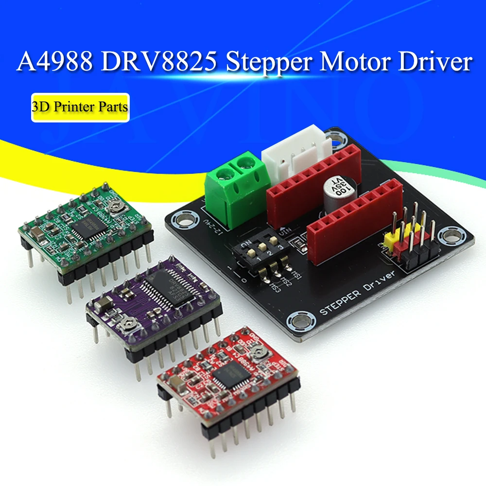
The A4988 and DRV8825 Stepper Motor Driver modules are essential control components for precision motion applications, particularly within 3D printing and CNC systems. These drivers offer granular control over stepper motors, translating digital signals into precise mechanical movements. As a certified electrician, the immediate focus is on the integrity of the electrical pathways and the thermal management solutions provided. The visible components suggest a standard yet effective design for managing motor current.
Each module integrates a dedicated stepper motor driver IC, along with supporting passive components and pin headers for interface. Heat sinks are included. This configuration allows for direct control of bipolar stepper motors, enabling microstepping capabilities that smooth out motor movement and reduce resonance. Precise positioning is crucial. The compact form factor is a significant advantage for integration into existing control boards.
Unlike basic motor control circuits that offer only full-step operation, these dedicated drivers provide advanced current control and microstepping, significantly enhancing the accuracy and quietness of motion systems. This upgrade from rudimentary control methods ensures smoother operation and finer detail in printed objects. The ability to fine-tune current limits is a key differentiator.
Component Integrity and Thermal Management
The visible circuit boards, typically FR-4 laminate, appear to be of standard quality for hobbyist and prosumer electronics. The soldering points on the pin headers and surface-mount components exhibit clean connections, which is critical for signal integrity and reliable power delivery. Poor solder joints can lead to intermittent operation or, worse, localized overheating. The modules are small. The pin headers are clearly labeled, aiding in correct installation and reducing the risk of miswiring, a common electrical hazard.
Thermal management is addressed by the inclusion of small aluminum heat sinks. These are designed to dissipate heat generated by the driver ICs during operation, especially under higher current loads. Without adequate cooling, these ICs can quickly reach thermal shutdown thresholds, leading to skipped steps or complete motor stoppage. Overheating can damage components. Proper heat dissipation extends the lifespan of the driver and ensures consistent performance.
Compared to driver modules without dedicated heat sinks, or those relying solely on convection from the PCB, the inclusion of these heat sinks represents a proactive approach to thermal stability. This is particularly important in enclosed 3D printer environments where airflow might be restricted. The small size of the heat sinks implies they are suitable for moderate current applications, but users should always monitor temperatures during initial setup and heavy use.
Electrical Pathway and Current Handling
The expansion board, designed to host multiple driver modules, features screw terminals for the 12-24V input. These terminals are a critical interface for power delivery. The quality of these terminals directly impacts the safety and reliability of the power connection. Visually, they appear to be standard two-piece screw terminals, which, when properly tightened, provide a secure connection. Loose connections are dangerous. The board also includes a dedicated connector for the 42 stepper motor, ensuring a standardized and robust interface.
For an electrician, the primary concern with screw terminals is ensuring they can adequately handle the rated current without excessive heat buildup. While the exact current rating of these specific terminals is not explicitly stated, they are typically designed for the currents associated with NEMA 17 stepper motors. Users must verify wire gauge compatibility. Using undersized wire or improperly stripped wires can lead to high resistance, localized heating, and potential fire hazards. The board's traces must also be sufficiently wide to carry the current without undue voltage drop or heat.
Unlike soldered connections, screw terminals offer flexibility for installation and replacement but demand careful attention to torque specifications. Overtightening can strip threads or damage the wire, while undertightening can lead to arcing and poor contact. The visible design suggests a straightforward power distribution path, but the ultimate safety rests on the installer's adherence to best practices for electrical connections. Power stability is key.
Microstepping and Control Interface
Both A4988 and DRV8825 drivers support microstepping, a technique that divides each full step of a stepper motor into smaller increments. The A4988 typically offers up to 1/16 microstepping, while the DRV8825 can achieve up to 1/32 microstepping. This capability is configured via onboard DIP switches on the expansion board. These switches allow users to select the desired microstep resolution, directly impacting the smoothness and precision of motor movement. Finer steps reduce vibration.
The control interface consists of dedicated pins for 'Enable', 'Step', and 'Direction'. The 'Step' pin receives pulses that advance the motor by one microstep, while the 'Direction' pin determines the rotation direction. The 'Enable' pin activates or deactivates the driver. This standard interface simplifies integration with microcontrollers like Arduino or dedicated 3D printer control boards (e.g., SKR, RAMPS, MKS GEN). Clear labeling is provided.
This standardized control scheme is a significant advantage, as it allows for broad compatibility across various 3D printer and CNC platforms. Unlike proprietary motor control systems, these open-source compatible drivers offer flexibility and ease of replacement. The ability to easily adjust microstepping via physical switches on the expansion board provides a tangible benefit for users who experiment with different print resolutions or motor configurations. Configuration is straightforward.
Compatibility and System Integration
The product explicitly states compatibility with popular 3D printer control boards such as SKR V1.3, 1.4, GTR V1.0, RAMPS 1.4, 1.6, and MKS GEN V1.4. This broad compatibility is a major selling point, indicating that these drivers adhere to common pinout standards for stepper motor driver sockets. This ensures a plug-and-play experience for many users, minimizing complex wiring or adapter requirements. Integration is simplified.
For system builders, this compatibility means less time spent on custom wiring and more time on optimizing printer performance. The expansion board acts as a convenient hub, consolidating power and control signals for multiple drivers. This modular approach allows for easy upgrades or replacements of individual driver modules without needing to overhaul the entire control system. Modularity enhances maintenance.
Compared to integrated motor control solutions found on some entry-level boards, the modular nature of these drivers offers superior flexibility. If a driver fails, only that specific module needs replacement, not the entire motherboard. This reduces long-term maintenance costs and downtime. The ability to mix and match different driver types (A4988, DRV8825, TMC series) on the same expansion board, depending on specific motor requirements, provides an advanced level of customization for demanding applications.
Longevity and Maintenance Considerations
The longevity of these stepper motor drivers is primarily influenced by operating conditions, particularly temperature and current load. The included heat sinks are a good starting point for thermal management, but active cooling (e.g., a fan directed at the drivers) is highly recommended, especially when operating motors at their maximum rated current or in enclosed spaces. Consistent cooling prevents premature failure. Regular inspection of connections is also vital.
Maintenance involves ensuring the heat sinks remain securely attached and free of dust buildup, which can impede thermal transfer. Periodically checking the screw terminals for tightness is also a good practice, as vibrations from the printer can sometimes loosen connections over time. A loose connection can lead to arcing, which is a significant fire risk. Cleanliness and secure connections are paramount.
Unlike fully enclosed or potted electronic modules, these open-board designs allow for visual inspection and easier troubleshooting. However, they are also more susceptible to environmental factors like dust and humidity. Proper enclosure and ventilation are essential for maximizing their operational lifespan. The ability to easily swap out modules simplifies repair processes, reducing the overall cost of ownership compared to integrated solutions.
The Electrician's Perspective on Value
From an electrical safety and performance standpoint, these A4988 and DRV8825 driver modules, especially when paired with the expansion board, represent a reliable and cost-effective solution for stepper motor control. The clear labeling, standard interfaces, and inclusion of heat sinks address fundamental electrical considerations. The modular design allows for targeted upgrades and easier troubleshooting, which is invaluable in complex systems like 3D printers. This system offers robust control.
Imagine a 3D printer operating with unparalleled precision, laying down layers with smooth, consistent movements, free from the jitters and noise associated with less capable drivers. The peace of mind that comes from knowing your electrical connections are secure and your components are thermally managed allows for uninterrupted creative output. This setup empowers intricate designs. This is not merely a component purchase; it is an investment in the reliability and quality of your motion control system, ensuring your projects come to life with the exactitude they demand, print after print, without electrical compromise.