5S 21V Lithium Battery Protection Board
Official Store Deal
Expert Analysis Overview
Safeguarding Power Cells: An Engineering Examination
The 5S 21V Lithium Battery Protection Board is a critical electronic module engineered to safeguard 5-cell series lithium-ion battery packs, particularly those found in Makita-style power tools, from common electrical hazards. This board represents a foundational component for anyone engaged in the repair, custom assembly, or upgrade of battery packs where cell integrity and operational safety are paramount. Unlike rudimentary protection circuits that might offer only basic voltage cutoffs, this unit integrates comprehensive monitoring, a vital feature for preventing thermal runaway and extending the operational life of high-stress applications.
The Core Function: Voltage Regulation and Cell Balancing
At its operational heart, this protection board diligently manages the charge and discharge cycles of a 5S lithium-ion battery pack. It actively prevents overcharge by cutting off the charging current once any cell reaches its maximum safe voltage, typically 4.2V. This prevents irreversible damage to the cell's chemistry, which can lead to reduced capacity and premature failure. Overcharge protection is non-negotiable.
Conversely, the board implements over-discharge protection, disconnecting the load when any cell drops below a predetermined minimum safe voltage, often around 3.0V. Deep discharge can permanently degrade a lithium-ion cell's capacity and internal resistance, significantly shortening its lifespan. This protective measure ensures the battery remains within its healthy operational window.
Beyond simple voltage cutoffs, the board incorporates cell balancing. This critical function equalizes the voltage across all five cells in the series during the charging process. Without balancing, individual cells can drift in voltage, leading to some cells being overcharged while others are undercharged, ultimately limiting the pack's overall usable capacity and accelerating degradation. The visible balance leads on the board are direct indicators of this capability, offering a pathway for current to bypass higher-voltage cells until all cells reach a balanced state.
Thermal Guardianship: Integrated Protection Mechanisms
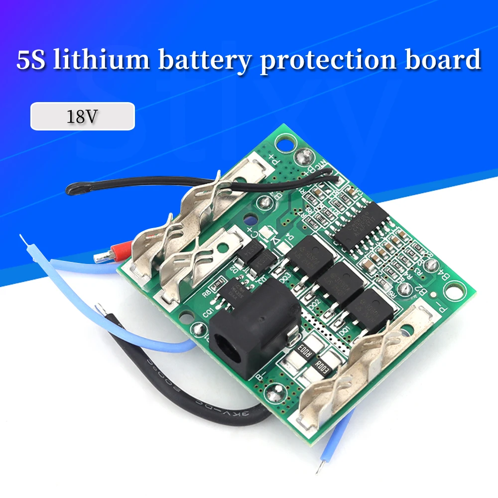
High-drain applications, such as power tools, generate significant heat within battery packs. Uncontrolled temperature can lead to thermal runaway, a dangerous condition where a cell rapidly overheats and can catch fire or explode. This 5S protection board integrates a temperature sensor, visible as a small black component on a wire, designed to monitor the battery pack's internal temperature.
Should the temperature exceed a safe operating threshold, the board will initiate a shutdown, preventing further charging or discharging until the temperature returns to a safe level. This thermal protection is an indispensable safety feature, particularly when the battery pack is subjected to heavy loads or rapid charging cycles. It adds a crucial layer of defense.
Furthermore, the board includes overcurrent protection. This mechanism detects when the current drawn by the load exceeds a safe limit, immediately disconnecting the battery to prevent damage to both the battery cells and the connected device. This is especially important in power tool applications where sudden stalls or heavy resistance can cause current spikes. Short circuit protection, a subset of overcurrent, provides an instantaneous cutoff in the event of a direct short, preventing catastrophic failure.
Structural Integrity and Connection Reliability
The physical construction of the 5S 21V Lithium Battery Protection Board reveals a green printed circuit board (PCB) with dimensions of approximately 40mm by 46mm. The layout appears organized, with various integrated circuits (ICs), MOSFETs, resistors, and capacitors strategically placed. The main power connections, typically labeled P+ and P-, feature larger solder pads, implying their design to handle higher current flows. These larger pads are essential for minimizing resistance and heat generation at the primary power interface.
Examination of the visible solder joints suggests machine assembly, which generally provides consistent quality. However, for DIY installations, the quality of the user's soldering will directly impact the board's reliability. Clean, well-formed solder joints are paramount for ensuring low resistance connections and preventing intermittent operation. The balance wire connections are smaller, designed for lower current signals, but their integrity is equally critical for effective cell balancing.
Component Selection and PCB Layout
The board's design incorporates multiple MOSFETs, which are power transistors responsible for switching the high currents during charge and discharge cycles. The number and rating of these MOSFETs are key indicators of the board's maximum continuous current capability. While specific ratings are not visually discernible, their presence in multiples suggests a design intended for moderate to high-power applications, consistent with power tool usage. The ICs present likely serve as the control logic for voltage monitoring, balancing, and protection triggering. These components work in concert to provide the board's advertised functionalities.
PCB traces, particularly for the main power paths, appear to be of adequate width for the expected current levels. Wider traces reduce resistance and heat buildup, contributing to the board's overall efficiency and longevity. The routing of balance lines, while not fully visible in detail, is crucial for maintaining signal integrity and accurate voltage readings across individual cells. A well-designed PCB minimizes noise and ensures precise monitoring, which is fundamental for effective battery management. This attention to layout detail is a sign of thoughtful engineering.
Interfacing with Power Tools: Compatibility Considerations
Marketed as