5.5x2.1mm DC Power Plug & Jack Connector Set
Official Store Deal
Expert Analysis Overview
The 5.5x2.1mm DC Power Connector Set is a foundational electrical component kit designed for low-voltage DC power distribution in hobbyist and light industrial applications. This collection of male plugs and female panel-mount jacks provides a standardized solution for connecting and disconnecting direct current power sources. Its utility extends across various projects requiring a reliable, yet easily integrated, power interface. The visible construction suggests a focus on functional utility rather than heavy-duty industrial resilience. This set offers a practical approach to managing power connections.
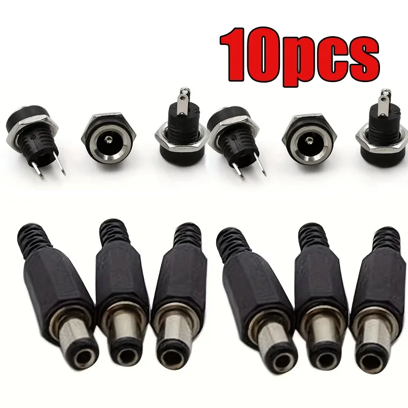
The visible components include black plastic housings for both the male plugs and female jacks, paired with metallic contact pins and sleeves. The male plugs feature a 5.5mm outer diameter barrel and a 2.1mm inner pin, a widely adopted standard for low-power DC devices. The female jacks are designed for panel mounting, incorporating a threaded body and a securing nut, as depicted in the visual evidence. These components are essential for creating robust power interfaces.
This material selection implies suitability for environments where physical stress is minimal. The plastic housing provides basic insulation and structural support. Metal contacts ensure electrical conductivity. The panel mount design allows for secure integration into enclosures, preventing accidental disconnections. This is crucial for project stability.
Compared to higher-grade industrial connectors, which often feature reinforced plastics, strain relief mechanisms, or even metal shells for enhanced durability and EMI shielding, these connectors represent a more economical and straightforward solution. They are not intended for high-vibration or extreme temperature applications. The design prioritizes ease of use and cost-effectiveness over ruggedization.
Examination of the male plugs reveals internal terminals designed for soldering, as shown in the detailed images. The female jacks also present solder tabs for wire attachment. Proper soldering is paramount for establishing a secure and low-resistance electrical connection. A poor solder joint can lead to increased resistance, heat generation, and potential power loss or failure. This is a critical installation step.
These connection points are where the electrical circuit is completed. The quality of the solder joint directly impacts the connector's ability to transmit current efficiently and safely. Over time, poorly soldered connections can degrade, leading to intermittent power or complete circuit breaks. Consistent power flow requires careful assembly.
Unlike crimp-style connectors that offer mechanical stability without heat, these solder-type connectors demand a skilled hand and appropriate tools for installation. The absence of integrated strain relief on the male plugs means that external cable management, such as heat shrink tubing or cable clamps, is advisable to prevent wire fatigue at the solder points. This extends component lifespan.
The 5.5x2.1mm standard is typically associated with low-voltage DC applications, commonly ranging from 5V to 24V. While no explicit current rating is provided, the physical dimensions of the metal contacts suggest suitability for currents generally below 5 Amperes. Exceeding this range without verification risks overheating and connector degradation. Proper load matching is vital.
Operating these connectors within their implied current limits ensures stable power delivery. Overloading can cause the internal contacts to heat up, potentially melting the plastic housing or leading to a fire hazard. This is a significant safety concern. Always verify the power requirements of the connected device. Undersized connectors are a common failure point.
In contrast to high-current power connectors, which feature larger gauge contacts and often specialized locking mechanisms to prevent accidental disconnection under load, these connectors are designed for less demanding scenarios. Their primary role is convenience and standardization for common electronic devices. They are not for heavy machinery. This distinction is important for safe application.
The panel-mount female jacks require a suitable cutout in an enclosure for installation. The threaded body and nut provide a secure mechanical attachment. The male plugs are designed for cable termination, necessitating proper wire stripping and soldering. Correct installation practices directly influence the operational lifespan of these connectors. A tight fit is essential.
When mounting the female jacks, ensuring the nut is adequately tightened prevents rotation and maintains a stable connection point. For the male plugs, the cable's outer jacket should be secured to prevent strain on the internal solder joints. This mechanical integrity is as important as the electrical connection. Loose connections invite trouble.
Many generic connectors in this category suffer from inadequate strain relief, leading to premature wire breakage. Users should consider adding external strain relief to the cable assembly, such as a cable gland or a simple zip tie, to mitigate this common failure mode. This proactive measure enhances overall system reliability. It protects the internal wiring.
This set of 10 pieces, comprising 5 male plugs and 5 female jacks, offers excellent value for hobbyists, DIY enthusiasts, and small-scale manufacturers. The standardized 5.5x2.1mm size ensures compatibility with a vast array of existing DC power adapters and devices. This versatility makes them a staple in any electronics workbench. They are highly adaptable.
Their low cost per unit allows for experimentation and prototyping without significant financial outlay. The ability to create custom power cables or repair existing ones provides practical utility. This kit supports a wide range of projects, from powering LED strips to custom circuit boards. It is a fundamental building block.
Unlike proprietary connector systems that lock users into specific brands or configurations, the open standard of 5.5x2.1mm connectors promotes interoperability. This reduces the complexity and cost associated with sourcing compatible power components. It is a universally recognized standard. This broad compatibility is a key advantage.
As a certified electrician, the primary concern with any electrical component is safety. These connectors, while simple, require adherence to fundamental electrical safety protocols. Always ensure power is disconnected before making or breaking connections. Incorrect wiring can lead to short circuits. This prevents electrical shock.
Proper insulation of all exposed wire and solder joints is non-negotiable. Heat shrink tubing or electrical tape should be used to cover any bare conductors. This prevents accidental contact and shorting. Double-checking polarity before applying power is also critical, as reverse polarity can damage sensitive electronic components. Polarity errors are common.
Furthermore, never exceed the implied current and voltage ratings of these connectors. While they appear robust for their intended use, pushing them beyond their design limits can result in overheating, melting, or even fire. Always match the connector to the load. Safety is paramount in all electrical work. This protects equipment and users.
Imagine completing your custom electronics project, knowing every power connection is secure and standardized. The panel-mounted jacks integrate cleanly into your enclosure, providing a professional finish. Your devices power on reliably, free from intermittent connections or overheating concerns, thanks to carefully soldered and properly rated components. This set provides the fundamental building blocks for dependable low-voltage power distribution, allowing your creations to function flawlessly and safely for years to come.
Anatomy of Power Delivery: Component Integrity
The visible components include black plastic housings for both the male plugs and female jacks, paired with metallic contact pins and sleeves. The male plugs feature a 5.5mm outer diameter barrel and a 2.1mm inner pin, a widely adopted standard for low-power DC devices. The female jacks are designed for panel mounting, incorporating a threaded body and a securing nut, as depicted in the visual evidence. These components are essential for creating robust power interfaces.
This material selection implies suitability for environments where physical stress is minimal. The plastic housing provides basic insulation and structural support. Metal contacts ensure electrical conductivity. The panel mount design allows for secure integration into enclosures, preventing accidental disconnections. This is crucial for project stability.
Compared to higher-grade industrial connectors, which often feature reinforced plastics, strain relief mechanisms, or even metal shells for enhanced durability and EMI shielding, these connectors represent a more economical and straightforward solution. They are not intended for high-vibration or extreme temperature applications. The design prioritizes ease of use and cost-effectiveness over ruggedization.
Terminal Connections and Current Pathways
Examination of the male plugs reveals internal terminals designed for soldering, as shown in the detailed images. The female jacks also present solder tabs for wire attachment. Proper soldering is paramount for establishing a secure and low-resistance electrical connection. A poor solder joint can lead to increased resistance, heat generation, and potential power loss or failure. This is a critical installation step.
These connection points are where the electrical circuit is completed. The quality of the solder joint directly impacts the connector's ability to transmit current efficiently and safely. Over time, poorly soldered connections can degrade, leading to intermittent power or complete circuit breaks. Consistent power flow requires careful assembly.
Unlike crimp-style connectors that offer mechanical stability without heat, these solder-type connectors demand a skilled hand and appropriate tools for installation. The absence of integrated strain relief on the male plugs means that external cable management, such as heat shrink tubing or cable clamps, is advisable to prevent wire fatigue at the solder points. This extends component lifespan.
Ensuring Reliable Power Transmission: Voltage and Amperage Considerations
The 5.5x2.1mm standard is typically associated with low-voltage DC applications, commonly ranging from 5V to 24V. While no explicit current rating is provided, the physical dimensions of the metal contacts suggest suitability for currents generally below 5 Amperes. Exceeding this range without verification risks overheating and connector degradation. Proper load matching is vital.
Operating these connectors within their implied current limits ensures stable power delivery. Overloading can cause the internal contacts to heat up, potentially melting the plastic housing or leading to a fire hazard. This is a significant safety concern. Always verify the power requirements of the connected device. Undersized connectors are a common failure point.
In contrast to high-current power connectors, which feature larger gauge contacts and often specialized locking mechanisms to prevent accidental disconnection under load, these connectors are designed for less demanding scenarios. Their primary role is convenience and standardization for common electronic devices. They are not for heavy machinery. This distinction is important for safe application.
Installation Considerations for Longevity
The panel-mount female jacks require a suitable cutout in an enclosure for installation. The threaded body and nut provide a secure mechanical attachment. The male plugs are designed for cable termination, necessitating proper wire stripping and soldering. Correct installation practices directly influence the operational lifespan of these connectors. A tight fit is essential.
When mounting the female jacks, ensuring the nut is adequately tightened prevents rotation and maintains a stable connection point. For the male plugs, the cable's outer jacket should be secured to prevent strain on the internal solder joints. This mechanical integrity is as important as the electrical connection. Loose connections invite trouble.
Many generic connectors in this category suffer from inadequate strain relief, leading to premature wire breakage. Users should consider adding external strain relief to the cable assembly, such as a cable gland or a simple zip tie, to mitigate this common failure mode. This proactive measure enhances overall system reliability. It protects the internal wiring.
Value Proposition and Application Versatility
This set of 10 pieces, comprising 5 male plugs and 5 female jacks, offers excellent value for hobbyists, DIY enthusiasts, and small-scale manufacturers. The standardized 5.5x2.1mm size ensures compatibility with a vast array of existing DC power adapters and devices. This versatility makes them a staple in any electronics workbench. They are highly adaptable.
Their low cost per unit allows for experimentation and prototyping without significant financial outlay. The ability to create custom power cables or repair existing ones provides practical utility. This kit supports a wide range of projects, from powering LED strips to custom circuit boards. It is a fundamental building block.
Unlike proprietary connector systems that lock users into specific brands or configurations, the open standard of 5.5x2.1mm connectors promotes interoperability. This reduces the complexity and cost associated with sourcing compatible power components. It is a universally recognized standard. This broad compatibility is a key advantage.
Safety Protocols and Electrical Best Practices
As a certified electrician, the primary concern with any electrical component is safety. These connectors, while simple, require adherence to fundamental electrical safety protocols. Always ensure power is disconnected before making or breaking connections. Incorrect wiring can lead to short circuits. This prevents electrical shock.
Proper insulation of all exposed wire and solder joints is non-negotiable. Heat shrink tubing or electrical tape should be used to cover any bare conductors. This prevents accidental contact and shorting. Double-checking polarity before applying power is also critical, as reverse polarity can damage sensitive electronic components. Polarity errors are common.
Furthermore, never exceed the implied current and voltage ratings of these connectors. While they appear robust for their intended use, pushing them beyond their design limits can result in overheating, melting, or even fire. Always match the connector to the load. Safety is paramount in all electrical work. This protects equipment and users.
Imagine completing your custom electronics project, knowing every power connection is secure and standardized. The panel-mounted jacks integrate cleanly into your enclosure, providing a professional finish. Your devices power on reliably, free from intermittent connections or overheating concerns, thanks to carefully soldered and properly rated components. This set provides the fundamental building blocks for dependable low-voltage power distribution, allowing your creations to function flawlessly and safely for years to come.