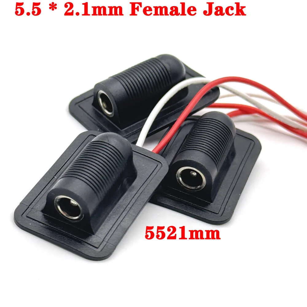
5.5x2.1mm DC Female Power Jack with Wired Leads
Official Store Deal
Expert Analysis Overview
Precision Power Integration: The 5.5x2.1mm DC Female Jack
The 5.5x2.1mm DC Female Power Jack with Wired Leads is a fundamental electrical component designed for secure, low-voltage power distribution in various DIY and professional applications. As a certified electrician, the immediate assessment focuses on the practical integration and safety implications of such pre-wired connectors. These jacks are engineered to provide a reliable interface for power input, particularly where a standard 5.5mm outer diameter and 2.1mm inner pin DC plug is utilized. Their pre-attached wiring simplifies installation, a critical factor for both hobbyists and industrial assemblers seeking efficiency and consistent performance.
Connection Integrity and Material Assessment
The visible terminals feature pre-soldered red and white wires, indicating a direct connection point. This pre-wired configuration simplifies installation, reducing the need for intricate soldering by the end-user. It minimizes potential cold solder joints and improves connection reliability. Unlike standard panel-mount jacks that require manual wiring, these integrated leads offer a plug-and-play advantage, saving significant assembly time and reducing labor costs in production environments. The plastic housing appears to be a standard ABS or similar polymer, offering adequate insulation for low-voltage applications. Its construction is straightforward.
Further examination of the connection points reveals a robust design for the female receptacle. The central pin and outer barrel are critical for consistent power transfer. The internal contacts must maintain firm pressure on the male plug to prevent intermittent connections or arcing, which can lead to power fluctuations or component damage. The visible metal components suggest a standard brass or nickel-plated brass construction, common for such connectors. This material choice provides a balance of conductivity and corrosion resistance for typical indoor environments. For outdoor or high-humidity applications, additional environmental sealing would be necessary, as the current design does not appear to offer inherent waterproofing.
Wire Gauge and Current Handling Capabilities
The red and white wires attached to the DC jacks are a crucial aspect for electrical safety and performance. Based on visual estimation, these appear to be in the range of 20-24 AWG (American Wire Gauge). This gauge is suitable for low-current applications, typically up to 1-2 Amperes, depending on the length of the wire run and ambient temperature. Exceeding these limits can lead to wire overheating, insulation degradation, and potential fire hazards. Proper wire sizing is paramount. Users must always verify the current draw of their connected devices against the wire's rated capacity. For higher current demands, a larger gauge wire would be indispensable, or multiple connectors could be used in parallel with appropriate load balancing.
In a scenario where a device draws 3 Amperes, using these connectors with their likely 22 AWG wires could pose a significant risk. The voltage drop across the wire would also increase, potentially starving the connected device of adequate power. This could lead to erratic operation or premature failure of the device. Compared to custom-wired solutions where the installer can select the exact wire gauge for the application, these pre-wired units offer convenience but necessitate careful consideration of the load. Always check specifications. The absence of explicit wire gauge or current rating on the product images means users must exercise caution and perform their own calculations or tests. This is a critical safety step.
Durability and Installation Considerations
The rectangular base of the connector is designed for surface mounting, providing a stable platform for installation. The four corners of the base likely accommodate small screws or adhesive for secure attachment to a chassis, panel, or project enclosure. This mounting method ensures the jack remains fixed, preventing strain on the soldered wire connections during repeated plug insertions and removals. A secure mount is vital. The ribbed texture on the cylindrical part of the jack suggests a design intended for improved grip during handling or potentially for a threaded panel-mount application, though the flat base indicates surface mounting is the primary intent.
The overall construction appears to prioritize ease of use and basic functionality over extreme ruggedness. While suitable for internal wiring within enclosures or light-duty external applications, these connectors are not designed for environments subject to heavy mechanical stress, vibration, or frequent impacts. For industrial machinery or outdoor installations, more robust, sealed, and strain-relieved connectors would be required. The simplicity of the design, however, makes them highly adaptable for prototyping, educational projects, and consumer electronics repair. Their compact footprint allows for integration into tight spaces, a common requirement in modern electronic designs. Proper installation enhances longevity.
Electrical Safety and Polarity
Electrical safety is non-negotiable. The red and white wire color coding typically indicates positive and negative polarity, respectively, in DC circuits. However, industry standards can vary, and it is imperative for the user to verify the actual polarity of the jack's internal connections using a multimeter before connecting any device. Incorrect polarity can instantly damage sensitive electronics. This verification step is crucial for preventing costly mistakes and ensuring the longevity of connected components. A quick continuity test confirms the internal wiring.
Furthermore, the insulation on the wires appears to be standard PVC, which offers good dielectric strength for low-voltage applications. However, it is not typically rated for high temperatures or harsh chemical environments. Users should ensure that the wires are routed away from heat sources and sharp edges to prevent insulation damage. Any compromise to the insulation can lead to short circuits, electrical shock, or fire. Unlike UL-listed or CE-marked cables with explicit voltage and temperature ratings, these generic components require the installer to assume responsibility for their safe application. Due diligence is essential. Always double-check connections.
Value Proposition and Application Scenarios
These 5.5x2.1mm DC female jacks offer significant value for their price point, especially when purchased in multi-packs. Their primary benefit lies in simplifying the power input stage for various electronic projects. Consider a scenario where a user is building a custom LED lighting system, a small amplifier, or a microcontroller-based device. These pre-wired jacks eliminate the need for soldering small, fiddly components, thereby accelerating assembly time and reducing the barrier to entry for less experienced builders. The cost-effectiveness is clear.
Their application extends to repairing existing devices where the original DC jack has failed. Replacing a damaged jack with a pre-wired unit can be far quicker and less complex than desoldering and resoldering a bare component. This translates to reduced repair time and potentially lower repair costs. The convenience factor is a major selling point. While not suitable for every high-power or extreme-environment application, for the vast majority of low-voltage DC power requirements, these connectors provide a practical, efficient, and economical solution. They are a staple in any electronics workshop. Imagine completing your project faster, with fewer soldering headaches, and a reliable power connection that simply works.
Technical Specifications Overview
Connector Dimensions and Compatibility
The core specification of 5.5mm x 2.1mm refers to the outer diameter of the barrel and the inner diameter of the central pin, respectively. This is a widely adopted standard for low-voltage DC power supplies, making these jacks compatible with a vast array of wall adapters, power bricks, and battery packs. This broad compatibility is a significant advantage, as it reduces the need for specialized power solutions. The physical dimensions of the rectangular mounting base are approximately 25mm x 15mm, providing a compact footprint for integration into various enclosures. Its small size is beneficial.
Electrical Ratings and Performance
While specific current and voltage ratings are not explicitly provided in the visual data, similar connectors typically handle up to 12V-24V DC and currents ranging from 1A to 3A. Users must operate within these estimated parameters to ensure safe and reliable performance. Overcurrent conditions will lead to excessive heat generation, which can melt the plastic housing or damage the internal contacts. The pre-attached wires, likely 20-24 AWG, are the limiting factor for current capacity. Always verify the load. The contact resistance of the internal mechanism is generally low, ensuring efficient power transfer with minimal energy loss. This contributes to the overall efficiency of the power delivery system.
Environmental Considerations
These connectors are designed for indoor, dry environments. They do not feature any explicit IP (Ingress Protection) rating, meaning they are not sealed against dust or moisture. Exposure to water or high humidity can lead to short circuits, corrosion of contacts, and premature failure. For applications requiring environmental protection, additional sealing, such as potting or using waterproof enclosures, would be necessary. The operating temperature range is typically standard commercial grade, from 0°C to 70°C. Extreme temperatures can affect the plastic housing and wire insulation. Proper environmental management is key.
Installation and Maintenance Protocol
Secure Mounting Procedures
Proper mounting is essential for long-term reliability. The rectangular base should be affixed to a flat, stable surface using small screws or a strong adhesive. Ensure the mounting surface is clean and free of debris for optimal adhesion. Avoid overtightening screws, which can crack the plastic base. The connector must be stable. A secure mount prevents mechanical stress on the wire connections and the jack itself, extending its operational lifespan. This also ensures consistent contact with the male plug.
Polarity Verification Steps
Before connecting the jack to any power source or device, always verify the polarity of the red and white wires using a multimeter. Connect the multimeter in DC voltage mode to a known power supply. Touch the red probe to the red wire and the black probe to the white wire. A positive voltage reading confirms the red wire is positive and the white wire is negative. If a negative voltage is displayed, the polarity is reversed. This step prevents damage. Correct polarity is critical for sensitive electronics.
Wire Management and Strain Relief
Route the attached wires carefully, avoiding sharp bends, pinching, or proximity to heat sources. Use cable ties or clips to secure the wires, providing strain relief to prevent accidental tugging from damaging the soldered connections inside the jack. Proper wire management reduces the risk of short circuits and ensures a neat, professional installation. Strain relief is often overlooked. This also minimizes the chance of accidental disconnections.
Current Load Monitoring
Continuously monitor the current draw of the connected device, especially during initial setup and under varying operational conditions. Ensure the total current does not exceed the estimated capacity of the wires (e.g., 1-2A for 22 AWG). If the wires become noticeably warm to the touch, it indicates an overcurrent condition, requiring immediate disconnection and reassessment of the power requirements or wire gauge. Overheating is a fire risk. This vigilance prevents component failure and ensures safety.
Frequently Asked Questions for DC Power Jacks
Common Concerns and Expert Answers
Users often have questions regarding compatibility, installation, and safety. Addressing these proactively ensures a smoother experience and reduces potential issues. The following FAQs cover the most common inquiries.
What does "5.5x2.1mm" mean for this DC jack?
This specification refers to the physical dimensions of the connector. The "5.5mm" is the outer diameter of the barrel, and "2.1mm" is the inner diameter of the central pin. This is a very common size for low-voltage DC power adapters and devices.
Can these jacks handle high current applications?
No, these jacks are generally designed for low-current applications, typically up to 1-3 Amperes, depending on the wire gauge. The visible wires appear to be 20-24 AWG, which limits their current handling capacity. For higher current, larger gauge wires and more robust connectors are required.
How do I determine the correct polarity for these wires?
Always use a multimeter to verify polarity. Connect the multimeter in DC voltage mode to a known power source. Touch the red probe to the red wire and the black probe to the white wire. A positive voltage reading confirms red is positive and white is negative. If the reading is negative, the polarity is reversed.
Are these connectors waterproof for outdoor use?
No, these connectors are not inherently waterproof. They lack an IP rating and are designed for indoor, dry environments. For outdoor or high-humidity applications, additional sealing, such as potting or using a waterproof enclosure, is necessary to prevent moisture ingress and potential short circuits.
What is the best way to mount these jacks securely?
The rectangular base is designed for surface mounting. Use small screws or a strong adhesive to attach the base to a flat, stable surface like a chassis or project enclosure. Ensure the mounting surface is clean. This prevents mechanical stress on the connections and ensures the jack remains fixed during use.
Critical Safety Warnings
Preventing Electrical Hazards
Electrical components, even low-voltage ones, require careful handling to prevent hazards. Adherence to safety protocols is not optional. These warnings highlight critical areas for attention.
Conclusion: A Practical Choice for DC Power
These 5.5x2.1mm DC Female Power Jacks with Wired Leads represent a practical and efficient solution for integrating power into various electronic projects. Their pre-wired design significantly streamlines the assembly process, reducing the time and effort typically associated with soldering bare components. The standard dimensions ensure broad compatibility with existing DC power supplies, making them a versatile addition to any electronics toolkit. While their current handling is suited for low-power applications, and environmental sealing is not inherent, their value in terms of convenience and cost-effectiveness is undeniable. For those building, repairing, or prototyping devices that require a reliable, easy-to-implement DC power input, these connectors offer a compelling option. Imagine the satisfaction of quickly integrating power into your next project, knowing the connection is secure and efficient, allowing you to focus on the core functionality of your design rather than wrestling with intricate wiring.