28BYJ-48 Stepper Motor Kit with ULN2003 Driver Board
Official Store Deal
Expert Analysis Overview
Precision Motion Control for Micro-Applications
The 28BYJ-48 Stepper Motor Kit is a fundamental electromechanical assembly, critically evaluated for precise angular positioning in low-power applications. This kit provides a complete solution for hobbyists and educators seeking to implement controlled rotational movement. The combination of a unipolar stepper motor and a ULN2003 driver board simplifies integration into microcontroller projects.
Motor Specifications and Operational Principles
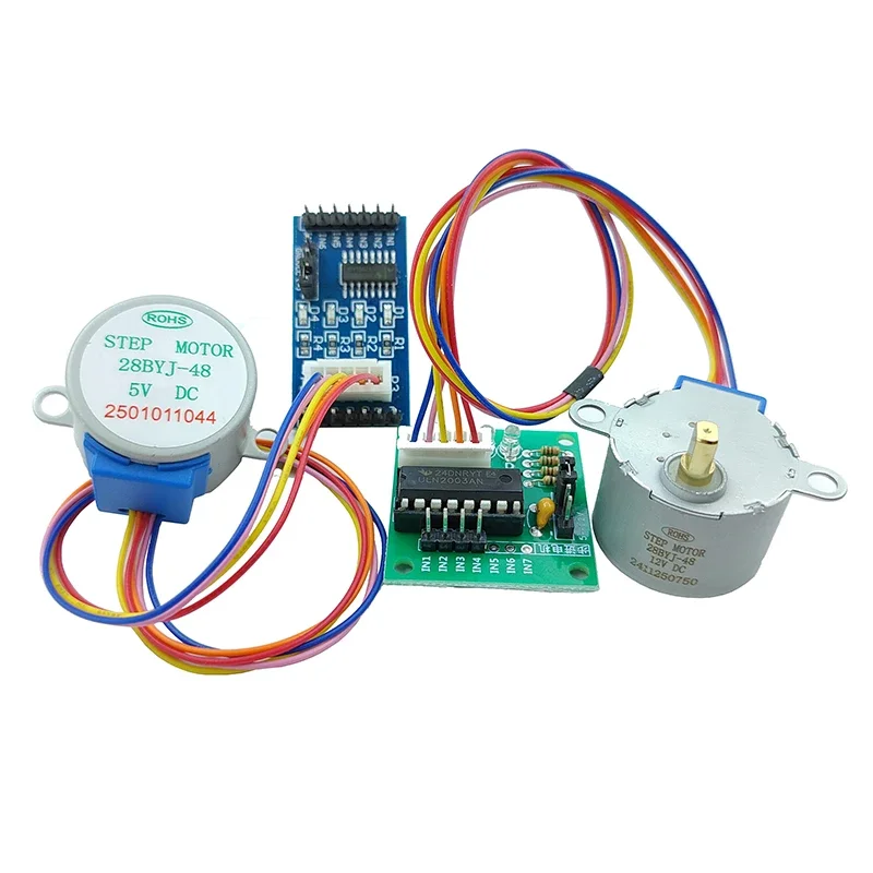
The visible stepper motors are identified as 28BYJ-48 models, typically operating at either 5V DC or 12V DC, as indicated by the product title and visible markings. These are 4-phase unipolar stepper motors. A unipolar stepper motor simplifies control circuitry. Each phase coil has a center tap, allowing current to flow in only one direction through each half of the coil. This design simplifies the driving logic, requiring only a single transistor per coil half to energize it. The 28BYJ-48 designation often implies a step angle of 5.625 degrees, which, when combined with its internal gearing, results in a much finer effective step angle, typically around 0.08789 degrees per step. This fine resolution is crucial for applications demanding smooth, incremental motion.
This configuration allows for granular control in small-scale automation projects. The motor's internal gearing significantly increases its effective resolution. This mechanical advantage also boosts the output torque, making it suitable for moving light loads with precision. The motor's compact form factor is a notable advantage. Its small size enables integration into confined spaces, which is often a requirement in prototype development or miniature robotics. The motor's construction appears robust for its intended use, with a metal casing providing structural integrity and heat dissipation for the internal windings. Proper heat management prevents premature component failure.
Unlike larger NEMA-rated steppers, this unit prioritizes compactness over raw torque. Industrial-grade stepper motors, such as NEMA 17 or NEMA 23, are designed for significantly higher torque and continuous operation under heavy loads. They often require more complex bipolar drivers and higher current supplies. The 28BYJ-48, by contrast, is optimized for low-power, low-torque scenarios where precise positioning is paramount. Its lower current draw makes it compatible with standard microcontroller I/O pins, albeit through a driver board. This distinction is critical for project planning, ensuring the motor's capabilities align with application requirements.
The ULN2003 Driver Board: Amplification and Protection
The kit includes a ULN2003 driver board, which is an essential component for interfacing the stepper motor with a microcontroller. The ULN2003 is a high-voltage, high-current Darlington transistor array. It contains seven NPN Darlington pairs, each capable of sinking up to 500mA and handling voltages up to 50V. For a 4-phase stepper motor, typically four of these Darlington pairs are utilized. The driver board acts as an intermediary, taking low-current control signals from a microcontroller (like an Arduino) and amplifying them to provide the necessary current to energize the motor's coils. This amplification is critical. Microcontroller pins typically cannot supply enough current directly to drive a motor, risking damage to the microcontroller itself.
The driver board protects the microcontroller from inductive kickback. When the current to a motor coil is switched off, the collapsing magnetic field generates a voltage spike (inductive kickback). The ULN2003 incorporates internal flyback diodes connected to a common COM pin. These diodes provide a path for this inductive energy to dissipate safely, preventing it from damaging the driver IC or the connected microcontroller. The board typically features a 5-pin header for connecting the motor and a 4-pin header for control signals from the microcontroller. Power input is usually via a 2-pin header or screw terminals, providing the 5V or 12V DC required by the motor.
Compared to direct transistor switching, the ULN2003 offers a pre-packaged, integrated solution. Building a discrete driver circuit with individual transistors and flyback diodes would be more complex and prone to wiring errors for beginners. The ULN2003 board simplifies the setup, reducing component count and board space. It also ensures consistent performance across all phases, which is vital for smooth stepper motor operation. While more advanced stepper drivers offer microstepping capabilities for even finer resolution and quieter operation, the ULN2003 provides a cost-effective and robust solution for basic full-step and half-step driving modes. Its widespread use in hobbyist projects attests to its reliability and ease of use.
Wiring and Electrical Integrity
The wiring supplied with the motor and driver board appears to be standard multi-strand hook-up wire, typically 26-28 AWG. The insulation on the wires appears to be PVC, which is common for low-voltage, low-current applications. The color coding (red, orange, yellow, blue, pink for the 5-wire motor) is standard for 28BYJ-48 motors, facilitating correct phase connection to the driver board. The connectors are JST-style, ensuring a secure and reversible connection. These connectors are widely used in electronics. The quality of the crimps on the terminals is critical for reliable electrical contact. Poor crimps can lead to intermittent connections, increased resistance, and potential overheating.
Proper wire gauge selection is paramount for electrical safety and performance. For the low currents typically drawn by a 28BYJ-48 motor (often in the range of 100-300mA per phase), the visible wire gauge is generally adequate. Using undersized wires can lead to excessive voltage drop, reducing the motor's effective torque, and more critically, can cause the wires to overheat. Overheating wires pose a significant fire hazard, especially in enclosed spaces or near flammable materials. The insulation rating, while not explicitly visible, is assumed to be appropriate for the 5V/12V DC operation. It is essential that the insulation remains intact and free from nicks or abrasions to prevent short circuits.
Compared to industrial wiring standards, these wires are designed for prototyping. Industrial applications often require higher gauge wires, specialized insulation (e.g., Teflon, silicone) for extreme temperatures or harsh environments, and robust connectors with locking mechanisms. For hobbyist use, the provided wiring is generally sufficient, but users must exercise caution to avoid physical damage to the insulation. Regular inspection of connections and wiring integrity is a good practice. Ensuring all connections are firm and correctly polarized prevents operational issues and potential electrical faults. The simplicity of the wiring scheme, with clear color coding, minimizes the risk of incorrect connections for beginners.
Application and Value Proposition
This stepper motor kit is ideally suited for educational purposes, rapid prototyping, and small-scale automation projects. Its low cost and ease of integration with popular microcontrollers like Arduino make it an excellent choice for learning about stepper motor control, robotics, and mechatronics. Projects such as automated camera sliders, small robotic arms, precise valve control, or even simple clock mechanisms can benefit from this kit's capabilities. The ability to precisely control angular position is a significant advantage over continuous rotation DC motors, which require additional feedback mechanisms (like encoders) for positional accuracy. This kit provides a direct path to controlled motion without complex feedback loops.
The value proposition of this kit is exceptionally strong for its price point. For a minimal investment, users gain a complete motor and driver solution. This affordability lowers the barrier to entry for individuals interested in electronics and robotics. The widespread availability of tutorials and community support for the 28BYJ-48 and ULN2003 further enhances its value. Users can quickly find code examples and troubleshooting guides, accelerating their learning process and project development. The kit's simplicity means less time spent on complex wiring or driver design, allowing more focus on the application itself.
Imagine the satisfaction of seeing your first automated project come to life, a small robotic arm precisely picking up an object, or a camera smoothly panning across a scene, all controlled by the precise movements enabled by this reliable stepper motor kit. This kit empowers creators to translate digital commands into tangible, controlled physical actions, opening up a world of possibilities for innovation and learning in electronics and automation.