2.0mm Double Row Female Pin Header Socket Connectors (10-Pack)
Official Store Deal
Expert Analysis Overview
The 2.0mm Double Row Female Pin Header Socket Connectors are essential passive electrical components designed for reliable signal and low-power interconnections in compact electronic assemblies. These connectors address the common frustration of unreliable or poorly fitting generic headers, providing a secure and consistent interface crucial for sensitive circuit paths. Investing in quality connectors like these prevents costly rework and troubleshooting, offering significant long-term value beyond their initial purchase price.
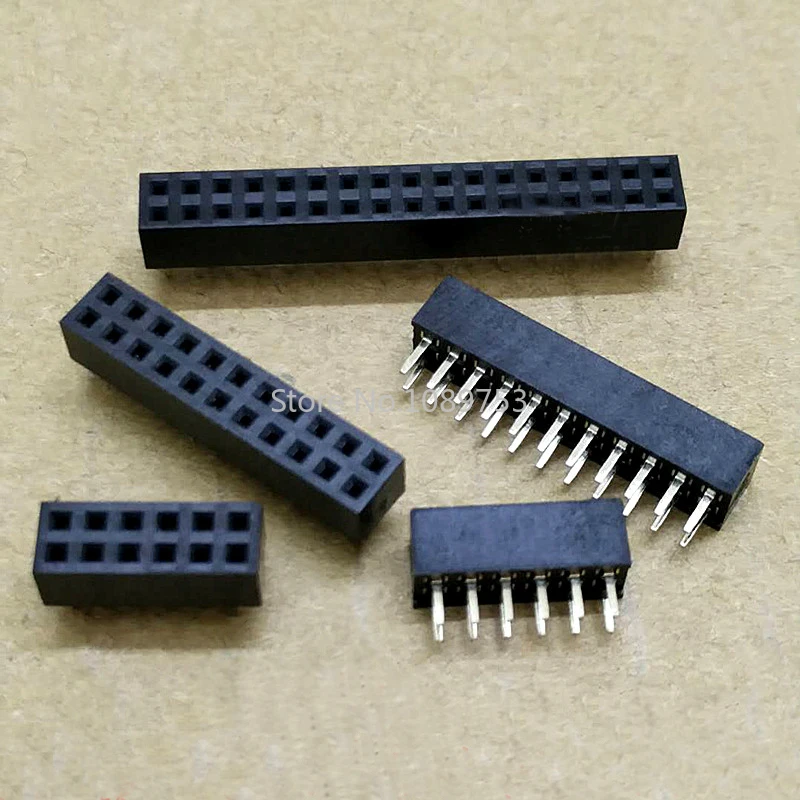
These connectors feature a precise 2.0mm pitch, a critical dimension for modern, miniaturized electronic designs. The double-row configuration is immediately visible, indicating a higher pin density compared to single-row alternatives. Black insulating housing encases the metal contacts, a standard practice for electrical isolation.
This specific pitch and double-row arrangement imply suitability for high-density signal routing and low-power distribution in space-constrained applications. Such designs are common in embedded systems, custom PCBs, and module-to-module interfacing where board real estate is at a premium. They are compact. The design prioritizes efficient use of space.
Compared to larger 2.54mm (0.1 inch) pitch connectors, the 2.0mm pitch allows for a significant reduction in overall connector footprint. This makes them a superior choice for projects demanding miniaturization without compromising the number of available connection points. Single-row headers offer less stability.
The visible housing material appears to be a robust insulating polymer, likely PBT (Polybutylene Terephthalate) or Nylon. These materials are chosen for their excellent dielectric strength, thermal stability, and mechanical resilience, ensuring the contacts remain isolated and the connector maintains its form under typical operating conditions. It is a solid build.
This material choice is critical for preventing electrical shorts and providing a stable mechanical platform for the metal contacts. The housing protects the delicate internal contacts from environmental factors and physical stress during insertion and extraction. Proper insulation is paramount for safety.
Unlike brittle, low-grade plastics that can crack or deform under minimal stress, the implied polymer construction offers enhanced durability. This translates to a longer operational lifespan and greater reliability in demanding applications. The material resists common solvents.
The internal metal contacts, visible as female sockets, are designed to receive male pins securely. While the specific metal alloy is not explicitly stated, industry standards for such connectors typically involve brass or phosphor bronze, often with tin plating. Tin plating enhances solderability and provides a degree of corrosion resistance. Contacts are crucial.
This contact design ensures a reliable electrical connection with low contact resistance, which is vital for maintaining signal integrity, especially in digital and analog signal paths. The spring-like action of the female contacts provides a consistent normal force against the male pins, minimizing intermittent connections due to vibration or minor movement. Good contact is essential.
Compared to direct wire soldering, these connectors offer modularity and ease of assembly/disassembly, while still providing a robust electrical path. The quality of the contact material and plating directly impacts the connector's ability to maintain low resistance over time, preventing signal degradation and power loss. They are engineered for consistency.
Given the 2.0mm pitch, these connectors are primarily intended for signal transmission and low-current power distribution. While no explicit current rating is provided, similar connectors typically handle between 1 to 2 Amperes per pin. Exceeding this can lead to localized heating and potential damage to the connector or connected components. Current capacity is limited.
This current handling capability makes them suitable for data lines, control signals, sensor interfaces, and small power rails within electronic circuits. They are not designed for high-power applications where larger gauge wires and more robust connectors are required. Proper application prevents overheating.
Unlike larger power connectors designed for high amperage, these 2.0mm headers prioritize density and signal fidelity. Using them within their intended current limits ensures stable operation and prevents thermal stress on the connector body and adjacent components. They excel in signal applications.
The product title indicates a wide range of available pin counts, from 2x2 (4 pins total) up to 2x25 (50 pins total). This extensive selection provides significant versatility for designers and engineers. A broad selection is available.
This adaptability means a single type of connector can be utilized across various modules and PCB designs, reducing the need to stock multiple connector types. It simplifies inventory management and offers flexibility during the prototyping phase, allowing for easy adjustments to pin configurations. Customization is straightforward.
This broad compatibility stands in contrast to fixed-count headers, which can limit design options or necessitate multiple distinct purchases. The availability of numerous pin counts makes these connectors a highly practical choice for diverse electronic projects. They fit many needs.
These are straight, through-hole mounted connectors, meaning their pins pass through holes in a Printed Circuit Board (PCB) and are typically soldered on the opposite side. This mounting method provides a strong mechanical connection to the PCB. Installation is direct.
Through-hole mounting offers excellent mechanical stability, making the connection resistant to vibration and physical stress once soldered. It is a reliable method for securing components to a PCB, particularly in applications where some physical robustness is required. Soldering ensures permanence.
Compared to surface-mount technology (SMT) connectors, through-hole components are generally easier to hand-solder and offer a more robust physical attachment to the board. This can be a significant advantage for hobbyists, educational settings, or low-volume production runs. They are easier to work with.
The design of these female header sockets, with their internal spring contacts, contributes to their long-term reliability. When properly mated with corresponding male pins, they form a secure and stable electrical junction. Reliability is key.
This secure connection minimizes the risk of intermittent signals, which can lead to unpredictable circuit behavior or system failures. The mechanical stability provided by the double-row configuration further enhances resistance to accidental disconnections or partial mating. Stable connections are vital.
Unlike temporary or less robust connection methods, these pin headers are designed for semi-permanent integration into electronic systems, providing a dependable interface for the lifespan of the device. They offer lasting performance. Imagine streamlined circuit development, robust module integration, and the confidence of secure electrical connections that stand the test of time, ensuring your projects function reliably from the first power-up to long-term operation.
Precision Interconnection: An Electrical Overview
These connectors feature a precise 2.0mm pitch, a critical dimension for modern, miniaturized electronic designs. The double-row configuration is immediately visible, indicating a higher pin density compared to single-row alternatives. Black insulating housing encases the metal contacts, a standard practice for electrical isolation.
This specific pitch and double-row arrangement imply suitability for high-density signal routing and low-power distribution in space-constrained applications. Such designs are common in embedded systems, custom PCBs, and module-to-module interfacing where board real estate is at a premium. They are compact. The design prioritizes efficient use of space.
Compared to larger 2.54mm (0.1 inch) pitch connectors, the 2.0mm pitch allows for a significant reduction in overall connector footprint. This makes them a superior choice for projects demanding miniaturization without compromising the number of available connection points. Single-row headers offer less stability.
Structural Integrity and Material Composition
The visible housing material appears to be a robust insulating polymer, likely PBT (Polybutylene Terephthalate) or Nylon. These materials are chosen for their excellent dielectric strength, thermal stability, and mechanical resilience, ensuring the contacts remain isolated and the connector maintains its form under typical operating conditions. It is a solid build.
This material choice is critical for preventing electrical shorts and providing a stable mechanical platform for the metal contacts. The housing protects the delicate internal contacts from environmental factors and physical stress during insertion and extraction. Proper insulation is paramount for safety.
Unlike brittle, low-grade plastics that can crack or deform under minimal stress, the implied polymer construction offers enhanced durability. This translates to a longer operational lifespan and greater reliability in demanding applications. The material resists common solvents.
Contact Design and Electrical Performance
The internal metal contacts, visible as female sockets, are designed to receive male pins securely. While the specific metal alloy is not explicitly stated, industry standards for such connectors typically involve brass or phosphor bronze, often with tin plating. Tin plating enhances solderability and provides a degree of corrosion resistance. Contacts are crucial.
This contact design ensures a reliable electrical connection with low contact resistance, which is vital for maintaining signal integrity, especially in digital and analog signal paths. The spring-like action of the female contacts provides a consistent normal force against the male pins, minimizing intermittent connections due to vibration or minor movement. Good contact is essential.
Compared to direct wire soldering, these connectors offer modularity and ease of assembly/disassembly, while still providing a robust electrical path. The quality of the contact material and plating directly impacts the connector's ability to maintain low resistance over time, preventing signal degradation and power loss. They are engineered for consistency.
Current Handling and Signal Fidelity
Given the 2.0mm pitch, these connectors are primarily intended for signal transmission and low-current power distribution. While no explicit current rating is provided, similar connectors typically handle between 1 to 2 Amperes per pin. Exceeding this can lead to localized heating and potential damage to the connector or connected components. Current capacity is limited.
This current handling capability makes them suitable for data lines, control signals, sensor interfaces, and small power rails within electronic circuits. They are not designed for high-power applications where larger gauge wires and more robust connectors are required. Proper application prevents overheating.
Unlike larger power connectors designed for high amperage, these 2.0mm headers prioritize density and signal fidelity. Using them within their intended current limits ensures stable operation and prevents thermal stress on the connector body and adjacent components. They excel in signal applications.
Versatility in Prototyping and Production
The product title indicates a wide range of available pin counts, from 2x2 (4 pins total) up to 2x25 (50 pins total). This extensive selection provides significant versatility for designers and engineers. A broad selection is available.
This adaptability means a single type of connector can be utilized across various modules and PCB designs, reducing the need to stock multiple connector types. It simplifies inventory management and offers flexibility during the prototyping phase, allowing for easy adjustments to pin configurations. Customization is straightforward.
This broad compatibility stands in contrast to fixed-count headers, which can limit design options or necessitate multiple distinct purchases. The availability of numerous pin counts makes these connectors a highly practical choice for diverse electronic projects. They fit many needs.
Installation Considerations for Optimal Performance
These are straight, through-hole mounted connectors, meaning their pins pass through holes in a Printed Circuit Board (PCB) and are typically soldered on the opposite side. This mounting method provides a strong mechanical connection to the PCB. Installation is direct.
Through-hole mounting offers excellent mechanical stability, making the connection resistant to vibration and physical stress once soldered. It is a reliable method for securing components to a PCB, particularly in applications where some physical robustness is required. Soldering ensures permanence.
Compared to surface-mount technology (SMT) connectors, through-hole components are generally easier to hand-solder and offer a more robust physical attachment to the board. This can be a significant advantage for hobbyists, educational settings, or low-volume production runs. They are easier to work with.
Long-Term Reliability in Electronic Systems
The design of these female header sockets, with their internal spring contacts, contributes to their long-term reliability. When properly mated with corresponding male pins, they form a secure and stable electrical junction. Reliability is key.
This secure connection minimizes the risk of intermittent signals, which can lead to unpredictable circuit behavior or system failures. The mechanical stability provided by the double-row configuration further enhances resistance to accidental disconnections or partial mating. Stable connections are vital.
Unlike temporary or less robust connection methods, these pin headers are designed for semi-permanent integration into electronic systems, providing a dependable interface for the lifespan of the device. They offer lasting performance. Imagine streamlined circuit development, robust module integration, and the confidence of secure electrical connections that stand the test of time, ensuring your projects function reliably from the first power-up to long-term operation.