15EDG PCB Screw Terminal Block Connectors
Official Store Deal
Expert Analysis Overview
Precision Interfacing: The 15EDG PCB Screw Terminal Block
The 15EDG PCB Screw Terminal Block is a fundamental, highly versatile electrical component designed for secure, removable wire-to-board connections in a multitude of electronic applications. This particular offering, featuring both 3.5mm and 3.81mm pitch options across a broad range of pin counts, targets engineers, technicians, and hobbyists who demand reliable, field-serviceable connections without the permanence of direct soldering. Its design prioritizes ease of installation and maintenance, making it an indispensable part of modern circuit design.
Core Design and Material Integrity
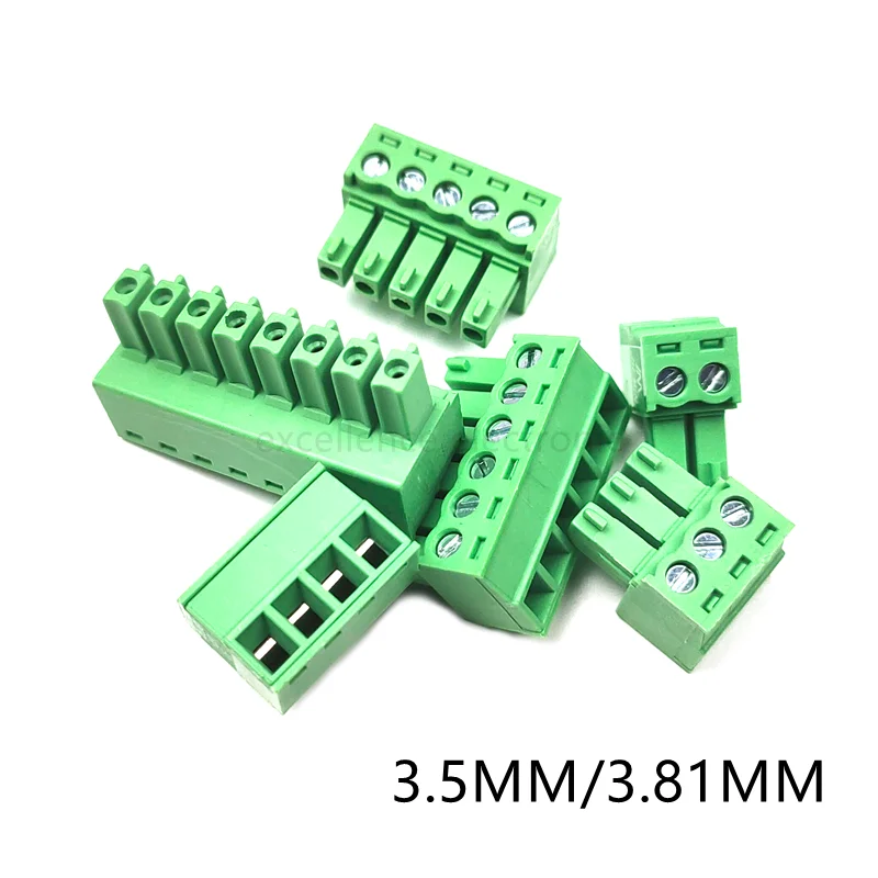
The visible components consist of a green plastic housing and metallic screw terminals. The green coloration is a common industry standard for terminal blocks, often indicating a specific material or application, though it primarily serves for visual identification. The plastic material, typically a polyamide (like PA66), provides essential electrical insulation and mechanical stability. This choice of material is critical for preventing short circuits and ensuring the long-term integrity of the connection, especially in environments where vibration or temperature fluctuations might compromise less robust plastics.
These terminal blocks are designed for direct mounting onto printed circuit boards (PCBs). The robust plastic housing protects the internal metal contacts and provides a stable platform for the screw mechanism. A well-engineered housing prevents accidental contact with live parts. This is a crucial safety feature in any electrical assembly.
Compared to cheaper, less specified alternatives, the implied material quality here suggests a commitment to basic electrical safety. Generic plastics can degrade under thermal stress or become brittle over time, leading to potential failures. The standard green appearance often correlates with materials that meet basic flame retardancy and dielectric strength requirements, offering a significant upgrade over uncertified components that pose fire risks.
Pitch Versatility and Pin Count Adaptability
The availability of both 3.5mm and 3.81mm pin pitches is a significant advantage. These two pitches are widely adopted standards in PCB design, allowing these connectors to integrate seamlessly into a vast array of existing and new projects. The 3.5mm pitch is often found in more compact designs, while 3.81mm offers slightly more spacing between terminals, which can be beneficial for higher voltage applications or when using slightly larger wire gauges.
This dual-pitch capability means designers are not constrained by a single standard. It provides flexibility during component selection, ensuring compatibility with various PCB layouts and existing footprints. This adaptability reduces the need to source multiple types of terminal blocks, streamlining inventory and procurement processes. It simplifies design choices for many projects.
Unlike single-pitch offerings that force designers to adapt their board layouts or compromise on component density, this dual-pitch solution directly addresses a common compatibility challenge. It effectively bridges the gap between different design philosophies and legacy systems, offering a more universal solution for wire termination on PCBs. This broad compatibility enhances project efficiency.
Furthermore, the extensive range of pin counts—from 2-pin to 12-pin configurations—caters to diverse circuit requirements. Whether a simple power connection, a multi-channel sensor interface, or a complex control signal array, a suitable pin count is available. This modularity allows for precise matching of the connector to the application's needs, minimizing wasted space and optimizing board layout.
This wide selection of pin counts ensures that designers can specify the exact number of connections required. It avoids the inefficiency of using a larger connector than necessary or the complexity of ganging multiple smaller connectors. This granular control over pin count is essential for efficient space utilization on crowded PCBs and for maintaining a clean, organized wiring scheme. It supports scalable designs.
Many generic terminal block assortments offer only a limited range of pin counts, often forcing compromises. This comprehensive selection, however, provides a distinct advantage by allowing for highly optimized and purpose-built solutions. It eliminates the need for workarounds, ensuring that every connection is precisely matched to its functional requirement, enhancing overall system reliability and aesthetics.
Secure Wire Termination and Electrical Safety
The screw-type terminal mechanism is a hallmark of reliability for wire connections. Each terminal features a metal screw that, when tightened, clamps down on the stripped end of a wire, creating a robust mechanical and electrical connection. This method is preferred in many industrial and hobbyist applications due to its security and ease of use. Proper tightening is key.
This screw-down action ensures a high-pressure contact between the wire and the terminal, which is crucial for minimizing resistance and preventing overheating. A secure connection reduces the risk of intermittent signals or power loss, which can lead to system malfunctions or, in severe cases, electrical fires. The visible screw heads suggest standard Phillips or slotted drive compatibility, facilitating common tool use. Verifying wire gauge accuracy is paramount for safe operation.
Compared to push-in or spring-clamp terminals, screw terminals often provide a more visually verifiable and mechanically stronger connection, especially for solid core wires or when higher current loads are anticipated. While push-in terminals offer speed, the tactile feedback and positive clamping action of a screw terminal provide an added layer of assurance regarding connection integrity. This method is time-tested.
Preventing electrical fires is a primary concern in any electrical design. The quality of the terminal connection directly impacts this. Loose or poorly made connections can generate heat due to increased resistance, potentially igniting surrounding materials. These screw terminals, when installed correctly with appropriate wire gauges, offer a reliable means to mitigate such risks. They are a critical safety component.
Furthermore, the design allows for easy inspection and re-tightening if necessary, a feature not always present in other connection types. This maintainability contributes significantly to long-term safety and operational reliability. Regular checks can identify and rectify potential issues before they escalate. This proactive approach saves time and prevents hazards.
Unlike flimsy, unrated terminals that might deform or lose clamping force over time, these standard-looking blocks imply a design intended for sustained performance. The visible metal components, likely brass or nickel-plated steel for corrosion resistance, suggest a commitment to maintaining electrical conductivity and mechanical strength over the product's lifespan. Checking terminal quality is a vital step.
Installation and Maintenance Considerations
Installation involves soldering the pin header socket to the PCB and then inserting the wire into the plug, securing it with the screw. This two-part design allows for easy disconnection of the wired harness from the PCB without disturbing the individual wire terminations. This modularity is invaluable for testing, maintenance, or field replacement of circuit boards. It simplifies servicing.
For prototyping or development, the ability to quickly connect and disconnect wires without desoldering is a major time-saver. In production environments, it facilitates modular assembly and simplifies troubleshooting. If a component on the PCB needs replacement, the entire wire harness can be removed and reconnected with minimal effort. This enhances efficiency.
Many direct-solder wire connections, while compact, lack this modularity, making repairs or modifications cumbersome and potentially damaging to the PCB. These terminal blocks offer a superior alternative by providing a robust, reusable interface that protects the underlying circuit board from repeated thermal stress. They extend board life.
Maintenance primarily involves ensuring the screws remain tight and that the wire insulation is intact right up to the terminal. Over time, vibrations or thermal cycling can sometimes loosen screw connections, necessitating periodic inspection and re-tightening. This simple maintenance procedure ensures continued optimal performance and safety. It is a straightforward task.
In a scenario where a wire needs to be replaced or reconfigured, the screw terminal allows for easy removal and re-insertion without specialized tools. This user-friendliness reduces downtime and the skill level required for basic field repairs. It empowers users to manage their own systems. This accessibility is a key benefit.
Compared to crimp connectors that require specialized tools for proper termination and are often single-use, these screw terminals offer a more forgiving and reusable connection method. The ability to easily modify wiring without destroying components or requiring proprietary tools makes them a more practical choice for many applications. This flexibility is highly valued.
Durability and Longevity
The implied construction, typical of these standard components, suggests a reasonable level of durability for their intended use. The plastic housing is designed to withstand typical operating temperatures and minor mechanical stresses. The metal components, including the screws and internal contacts, are generally chosen for their electrical conductivity and resistance to corrosion. They are built for purpose.
For applications in controlled environments, these terminal blocks can offer years of reliable service. Their longevity is largely dependent on proper installation, adherence to current ratings, and protection from excessive physical abuse or harsh chemical exposure. A well-designed enclosure further extends their lifespan. This protection is vital.
Unlike unbranded or extremely low-cost alternatives that might use inferior plastics or soft, easily stripped screws, these components, by their common design, are expected to meet basic industry standards for material quality. This ensures that the screws can be tightened adequately without stripping and that the plastic will not become brittle prematurely. This quality is fundamental.
The Certified Electrician's Perspective
From a certified electrician's standpoint, these 15EDG PCB screw terminal blocks represent a practical and safe solution for connecting external wiring to internal PCB circuitry. Their adherence to common pitch standards and wide pin count availability makes them highly adaptable. The screw-down mechanism, when properly utilized, provides a secure and inspectable connection, which is paramount for electrical safety. Always ensure the wire gauge matches the current requirements. The ability to easily disconnect and reconnect wiring simplifies troubleshooting and maintenance, reducing labor costs and potential hazards associated with permanent connections. These are solid components for many projects.
Imagine completing a complex control panel, knowing that every wire connection to your PCBs is not only secure but also easily accessible for future modifications or diagnostics. These terminal blocks provide that peace of mind, allowing for efficient assembly and reliable long-term operation. They empower you to build systems that are both robust and serviceable, ensuring your projects stand the test of time and meet safety standards with confidence.